Eureka AIR delivers breakthrough ideas for toughest innovation challenges, trusted by R&D personnel around the world.

Self-calibration for a catadioptric camera

a catadioptric camera and self-calibration technology, applied in the field of camera calibration, can solve the problems of image distortion, inability to capture the entire field of view, and large image detectors, and achieve the effects of accurate and thorough calibration, simple use, and accurate images

Inactive Publication Date: 2005-03-22
MICROSOFT TECH LICENSING LLC
View PDF3 Cites 36 Cited by
  • Summary
  • Abstract
  • Description
  • Claims
  • Application Information

AI Technical Summary

Benefits of technology

The system and method of the present invention is accurate and simple to use. In particular, the present invention is self-calibrating and uses images from a particular scene environment to calibrate the camera, thereby eliminating during calibration the need for calibration patterns, user-selected points, knowledge of camera motion or knowledge of the scene geometry. Moreover, the present invention is capable of determining a number of calibration parameters that ensure an accurate and thorough calibration so that the catadioptric camera system can produce accurate images of a particular scene.
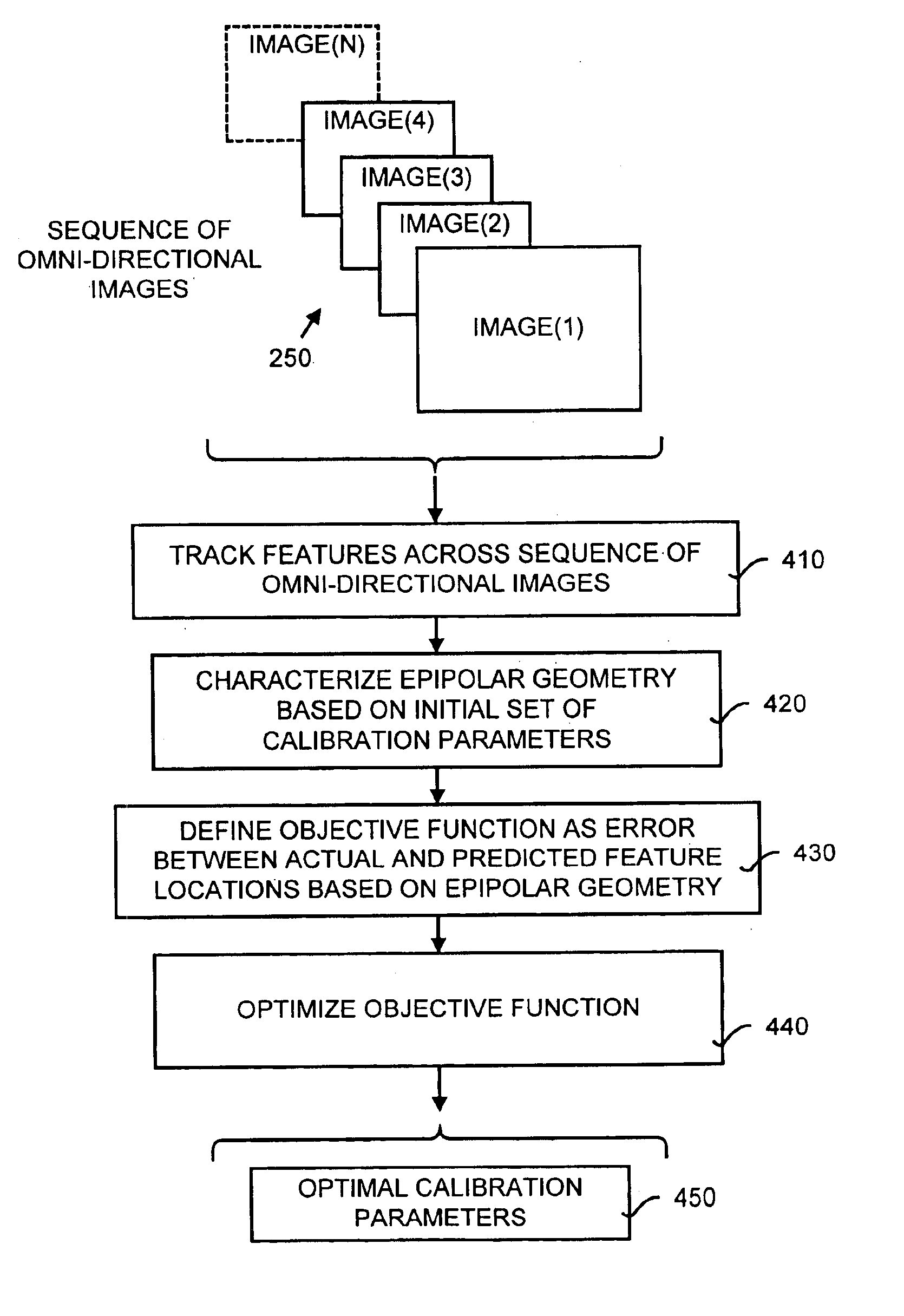
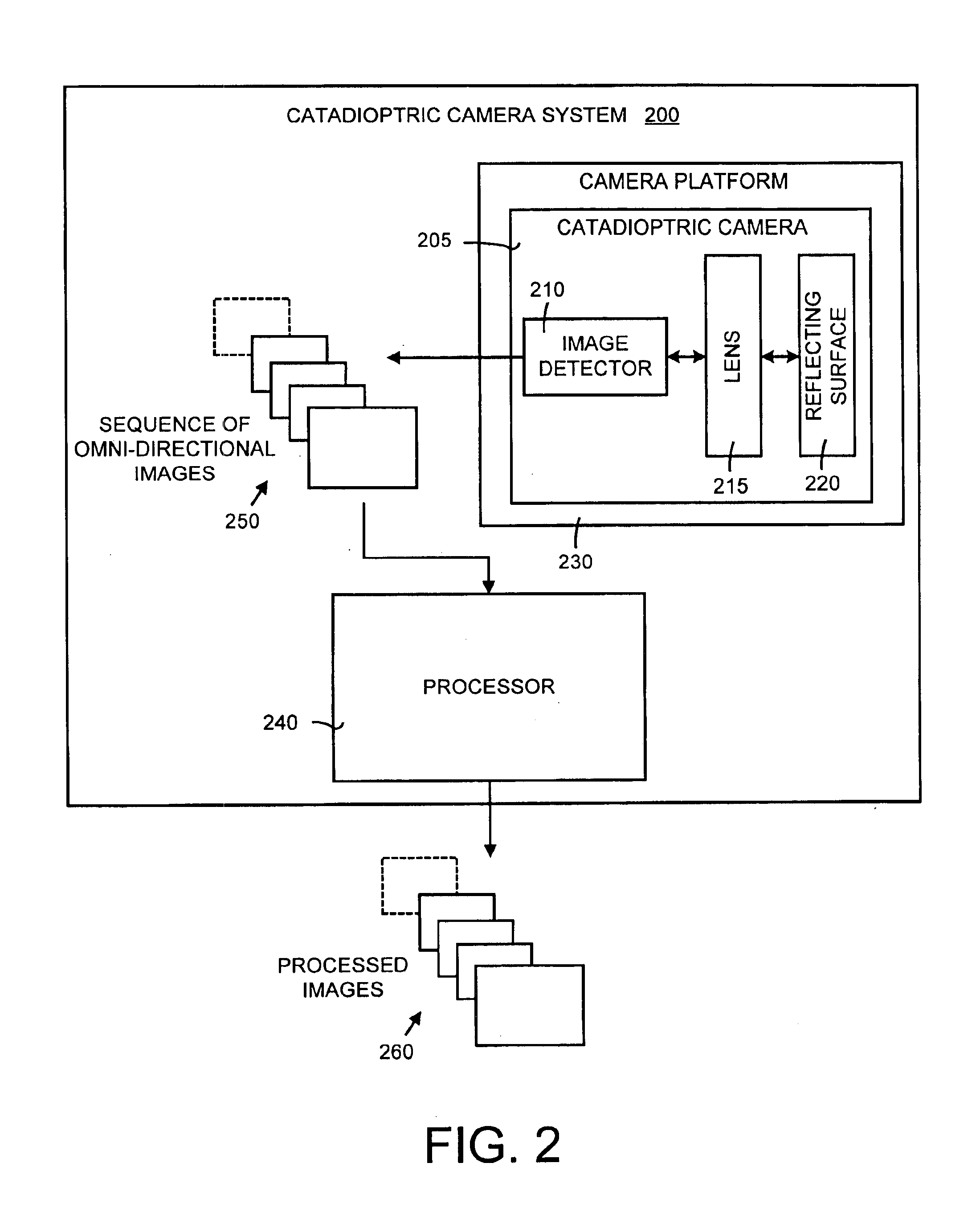
In general, the calibration method of the present invention self-calibrates a catadioptric camera by obtaining a sequence of omni-directional images representing a scene, tracking features across the sequence and estimating a set of calibration parameters based on catadioptric imaging characteristics. The estimation of calibration parameters is performed by establishing a relationship (such as an objective function) between the feature tracks and the calibration parameters and estimating the calibration parameters using an error metric. An optimization technique is used to minimize the error metric and recover an optimal set of calibration parameters. The present invention uses at least two techniques to recover the calibration parameters, including an algebraic error metric and a preferred and more robust image error metric. In addition, the present invention generally determines more calibration parameters than other calibration techniques including, for example, an aspect ratio and an image skew. The present invention also includes a system for self-calibrating a wide field-of-view camera using a sequence of omni-directional images that incorporates the method of the present invention. Moreover, the present invention includes a technique for reformulating a projection equation (such as used in the working example) such that the projection equation is equivalent to that of a typical rectilinear perspective camera. This allows analyses (such as structure from motion) to be applied in the same direct manner as for rectilinear image sequences.

Problems solved by technology

These reflecting surfaces, however, tend to cause image distortion.
Image distortion is inherent in a catadioptric camera because light rays at a periphery of the field of view are severely curved to allow the use of a smaller, inexpensive image detectors (such asia charge-coupled device or CCD).
Otherwise, prohibitively large and expensive image detectors would be needed to capture the entire field of view.
Unfortunately, however, these parameters are seldom known accurately and optical characteristics tend to vary between particular camera systems.
One disadvantage, however, of this technique is that the calibration pattern is large and using the pattern is awkward and time-consuming.
One disadvantage with this technique, however, is that the user must take the time to supply the calibration system with the data needed to correctly calibrate the camera.
In reality, both of these calibration techniques may be difficult to implement in consumer-based products because it is unlikely a consumer would want to or could correctly perform such complicated and time-consuming calibration techniques.
Moreover, if the camera calibration is performed incorrectly any results obtained from the camera will tend to be erroneous.

Method used


Image

  • Self-calibration for a catadioptric camera
  • Self-calibration for a catadioptric camera
  • Self-calibration for a catadioptric camera

Examples


working example

V. Details of the Invention and Working Example

FIG. 5 is a detailed flow diagram illustrating a working example of FIG. 4 of the present invention. This working example is provide for illustrative purposes and is only one of several ways in which the present invention may be implemented. The structural and mathematical details of this working example are discussed in detail below.

Referring to FIG. 5, a sequence of omni-directional images obtained from the catadioptric camera system is received as input (box 500). Next, point features are tracked across this sequence of images (box 510). Correspondences between point features across two different images are identified and used in the objective function to recover the calibration parameters (box 520). An objective function is defined as an error metric defined in terms of the deviation of pairwise correspondences from the epipolar geometry (box 530). The present invention includes two error metrics, both of which are defined in detail...


PUM


Abstract

A method and a system for self-calibrating a wide field-of-view camera (such as a catadioptric camera) using a sequence of omni-directional images of a scene obtained from the camera. The present invention uses the consistency of pairwise features tracked across at least a portion of the image collection and uses these tracked features to determine unknown calibration parameters based on the characteristics of catadioptric imaging. More specifically, the self-calibration method of the present invention generates a sequence of omni-directional images representing a scene and tracks features across the image sequence. An objective function is defined in terms of the tracked features and an error metric (an image-based error metric in a preferred embodiment). The catadioptric imaging characteristics are defined by calibration parameters, and determination of optimal calibration parameters is accomplished by minimizing the objective function using an optimizing technique. Moreover, the present invention also includes a technique for reformulating a projection equation such that the projection equation is equivalent to that of a rectilinear perspective camera. This technique allows analyses (such as structure from motion) to be applied (subsequent to calibration of the catadioptric camera) in the same direct manner as for rectilinear image sequences.

Description

BACKGROUND OF THE INVENTION1. Field of the InventionThe present invention relates in general to camera calibration and more particularly to a method and a system for self-calibrating a wide field-of-view camera (such as a catadioptric camera) using a sequence of omni-directional images of a scene obtained from the camera.2. Related ArtCameras having a wide field of view are important in several diverse applications. By way of example, wide field-of-view cameras are used in applications such as surveillance, video conferencing, multimedia-based applications (such as games), autonomous navigation, advertising (especially in the areas of real estate and tourism) and scene reconstruction. Wide field-of-view cameras are used to capture most or all of a region of interest (or scene) while using a minimum number of cameras.One type of wide field-of-view camera is a catadioptric camera. In general, a catadioptric camera uses a combination of reflecting surfaces (such as mirrors) and lenses ...

Claims


Application Information

Patent Timeline
Patent Type & Authority Patents(United States)
IPC IPC(8): H04N5/225H04N5/228G06T5/00G06T7/00H04N5/262H04N23/40
CPCG06T5/006H04N5/2628G06T7/0018G06T7/80G06T5/80
Inventor KANG, SING BING
Owner MICROSOFT TECH LICENSING LLC
Why Eureka
Eureka Blog
Learn More