
Dual-purpose pliers adapted to chain link

a technology of pliers and chains, applied in the field of pliers adapted to chain links, can solve the problems inconvenient operation, and achieve the effect of preventing the occurrence of chain pin slipping

Inactive Publication Date: 2011-06-30
WANG WEN PIN
View PDF7 Cites 19 Cited by
  • Summary
  • Abstract
  • Description
  • Claims
  • Application Information

AI Technical Summary

Benefits of technology

[0009]Therefore, the object of the present invention is to solve the aforementioned problems and to provide a kind of dual-purpose pliers adapted to chain link, which particularly includes the structure of curved brims disposed on jaw parts of the pliers tip sections and preferably represents the curved brims into serrated contour. Accordingly, the curved brims could densely lean against an arcuate surface of the chain pin and thence provides at least one arch enclosure therearound, so as to improve and prevent the occurrence of slipped chain pin.
[0022]1. The present invention efficiently spends less time and saves more labors while in use.
[0023]2. The present invention represents the dual-function pliers, and so facilitates a convenient manipulation and attains favorable detachment and assemblage without extra tools.
[0024]3. The curved brims or serrated configuration defined on the jaw parts substantially leans against the chain pin to avert the slipping problem.

Problems solved by technology

However, the typical master chain link facilely cause the chain pin slipped and inconvenient operation as a result of the pin formed of an arcuate contour that leads to the chain pin merely contacting with the jaw part of the pliers at one point.

Method used


Image

  • Dual-purpose pliers adapted to chain link
  • Dual-purpose pliers adapted to chain link
  • Dual-purpose pliers adapted to chain link

Examples


first embodiment

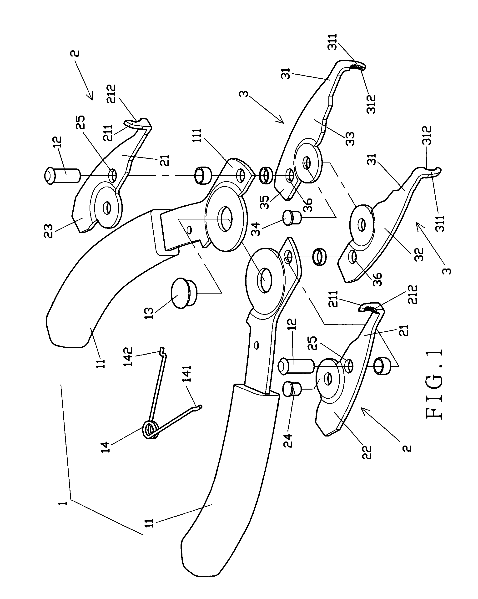
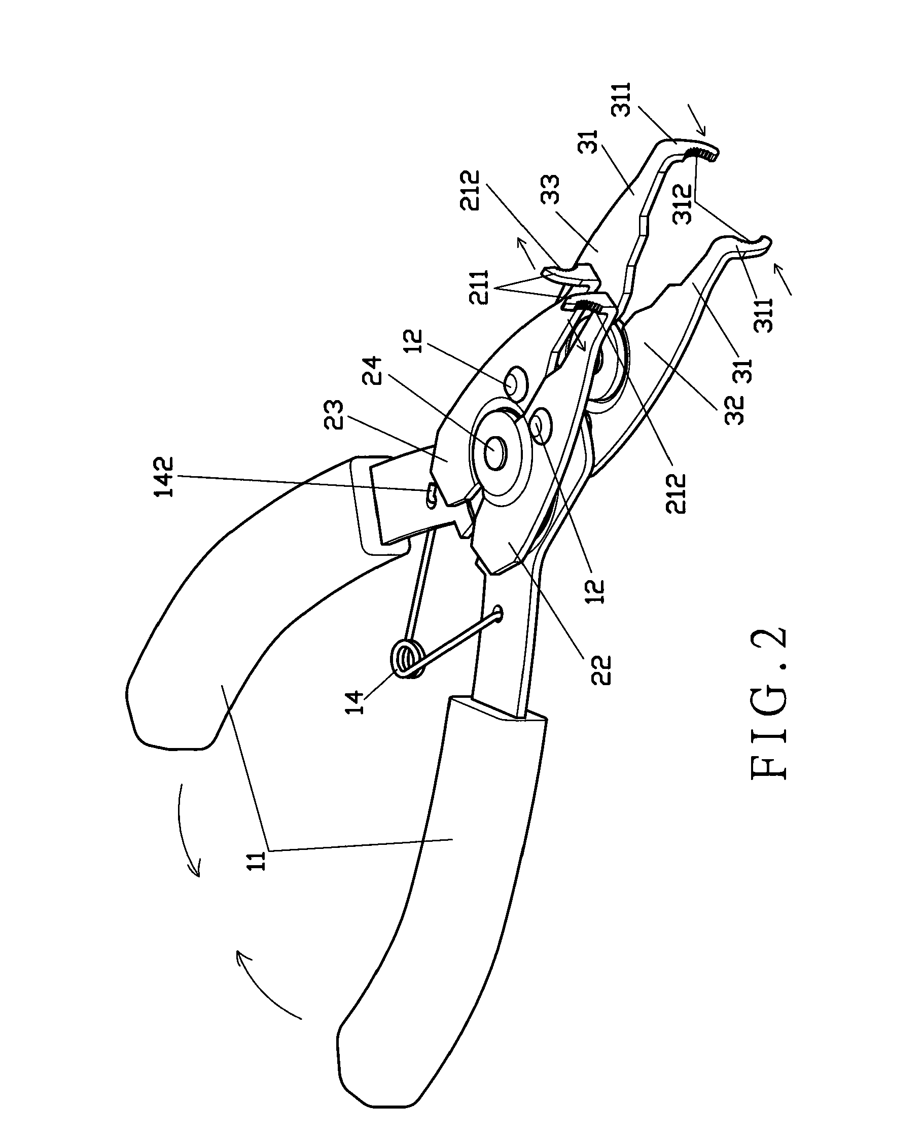
[0032]Still referring to FIGS. 1 to 3, the detail concatenation of interrelated elements of the subject dual-purpose pliers in accordance with the present invention includes a pliers handle 1, a first pliers body 2, and a second pliers body 3. The pliers handle 1 has two grasp portions 11, two fastening pins 12, a pivoting shaft 13, and a spring 14. Each of the two grasp portions 11 has one end 111 thereof fixed by the fastening pin 12 and pivotally engaged with the pivoting shaft 13 at a place adjacent to the fastening pin 12. The spring 14 located between the two grasp portions 11 includes two opposite ends 141,142 separately fixed to the two grasp portions 11. Furthermore, the first pliers body 2 includes a first left-side pliers plate 22, a first right-side pliers plate 23, and a first pivoting pin 24. The first left-side pliers plate 22 and the right-side pliers plate 23 have respective first tip sections 21, and the first left-side pliers plate 22 is coupled with the first rig...

third embodiment

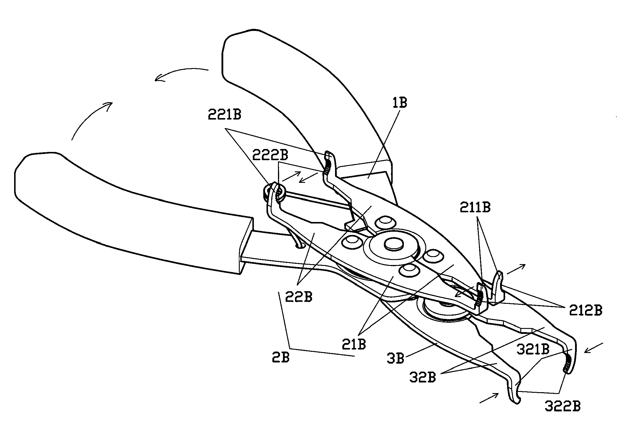
[0038]Referring to FIG. 6, the dual-purpose pliers in accordance with the present invention comprises a pliers handle 1B and two pliers bodies 2B,3B. The pliers handle 1B serves to connect and drive the pliers bodies 2B,3B. The two pliers bodies 2B,3B have opposite first tip sections 21B and second tip sections 22B,32B. Herein, the first tip sections of the pliers body 3B are covered by the pliers body 2B and are not labeled in the figure. The second tip sections 22B,32B of two pliers bodies 2B,3B are arranged in adverse directions, and so are the first tip sections. The first tip sections 21B respectively bend distal ends thereof to form two first jaw parts 211B extending from the distal ends and forms respective first curved brims 212B thereon, and the second tip sections 22B,32B respectively bend distal ends thereof to form two second jaw parts 221B,321B extending from the distal ends and forms respective second curved brims 222B,322B thereon. Further, the first curved brims 212B...


PUM


Abstract

A dual-purpose pliers adapted to chain link applies to concurrently promote a separation of two first jaw parts or an approach of two second jaw parts, which is conducive to a convenient detachment or assemblage of a master chain link via merely using a driving tool. Further, each jaw part forms a curved brim represented by an arcuate contour, a serrated shape, or the combination thereof. Accordingly, the curved brim serves to encircle and lean against a periphery of a chain pin of the chain for a stable manipulation.

Description

BACKGROUND OF THE INVENTION[0001]1. Field of the Invention[0002]The present invention relates to a pliers adapted to chain link, in particular a tool adapting to detach master chain link of the bicycle chain.[0003]2. Description of the Related Art[0004]A conventional chain link of the bicycle chain commonly adds an exterior link plate and disposes respective annular grooves on either end or both ends of a chain pin. Concerning to the assembling, a C-shape buckling part is disposed relative to the exterior plate, by which the plate could be clasped on the annular groove to prevent the escape of the chain pin.[0005]Further concerning to the detachment, the above typical invention needs to use specific tools to execute the dismantlement with following steps: initially fasten the chain link, force the exterior link plate to open, and thence extrude the chain pin out via a pusher. Such typical chain detacher is generally classified into IPC B21L 21 / 00.[0006]As in a prior invention, FIG. ...

Claims


Application Information

Patent Timeline
Patent Type & Authority Applications(United States)
IPC IPC(8): B25B7/02B25B7/12
CPCB25B7/02B25B27/0071B25B7/12
Inventor WANG, WEN-PIN
Owner WANG WEN PIN
Learn More