Recording apparatus and line type liquid discharge recording apparatus

a liquid discharge recording and recording apparatus technology, applied in other printing apparatus, printing, etc., can solve the problems of lowering suction capability, difficult to correct curl state on the leading end side of recording sheet, and difficulty in properly keeping the distance between recording head and recording sheet, so as to prevent lowering suction capability, and simple configuration

Inactive Publication Date: 2011-06-30
SONY CORP
View PDF5 Cites 31 Cited by
  • Summary
  • Abstract
  • Description
  • Claims
  • Application Information

AI Technical Summary

Benefits of technology

[0013]In view of the problems as described above, it is desirable to provide a recording apparatus and a line type liquid discharge recording apparatus, which can prevent lowering of suction power for a recording sheet.
[0020]According to the invention, when the recording sheet is transported over the platen section, the exposure opening portion of the shutter sheet sequentially opens the suction duct and the suction openings according to the position of the leading end of the recording sheet. Also, the exposure opening portion of the shutter sheet sequentially closes the suction duct and the suction openings according to the position of the back end of the recording sheet. Therefore, it is possible to prevent lowering of suction capability at the leading end and the back end of the recording sheet in a simple configuration.
[0021]Also, also in the width direction of the recording sheet, by removing suction from the suction openings which are not covered by the recording sheet, it is possible to prevent lowering of suction capability. In addition, it is possible to obtain effects such as suppression of discharge disturbance of ink by an air current which is generated from the suction opening, prevention of a noise caused by the air current, and prevention of drying of nozzle orifices by the air current.
[0022]Also, in the invention, also in a case where there are various sizes in the width direction of the recording sheets, it is possible to obtain the above-mentioned effects without necessitating a large space.
[0023]Also, in the invention, a recording sheet suction function, an idle discharge receiving function, a capping function, a moisturizing liquid supply function, and an ink mist collection function are provided together in the platen section. Therefore, in the invention, compared to a case where the respective functions are realized by separate components or mechanisms, a reduction in cost by a reduction in the number of components or an improvement in reliability by simplification of a mechanism becomes possible.

Problems solved by technology

In such a configuration in which a plurality of suction openings is provided in order to suck the recording sheet onto the surface of the platen, there is a problem in which suction capability is lowered when a leading end of the recording sheet passes over the platen.
In such a case, it is difficult to properly keep the distance between the recording head and the recording sheet.
For example, in such a case, it is difficult to correct a curl state occurring on the leading end side of the recording sheet.
In addition, problems occur such as an increase in noise due to generation of a sound by passage of external air through the suction openings which are not covered by the recording sheet, and lowering of impact precision due to disturbance of discharge of ink by an air current of the suction opening.
In such an ink jet printer, when recording is performed on the recording sheet of a width smaller than the maximum paper width, in the suction openings which are not covered by the recording sheet, air is leaked.
For this reason, in Japanese Unexamined Patent Application Publication No. 2007-152762, a problem occurs which is similar to the above-described case where the suction openings of a leading end portion of the recording sheet are not blocked.
However, in Japanese Unexamined Patent Application Publication No. 2004-098319, as many shielding plate movement mechanisms as the varieties of widths of the recording sheets are necessary, thereby leading to an increase in the cost of a recording apparatus or an increase in the size of the recording apparatus.

Method used


Image

  • Recording apparatus and line type liquid discharge recording apparatus
  • Recording apparatus and line type liquid discharge recording apparatus
  • Recording apparatus and line type liquid discharge recording apparatus

Examples


Embodiment Construction

[0046]Hereinafter, a line type ink jet printer apparatus will be described with reference to the drawings. In addition, application examples are described according to the following order.

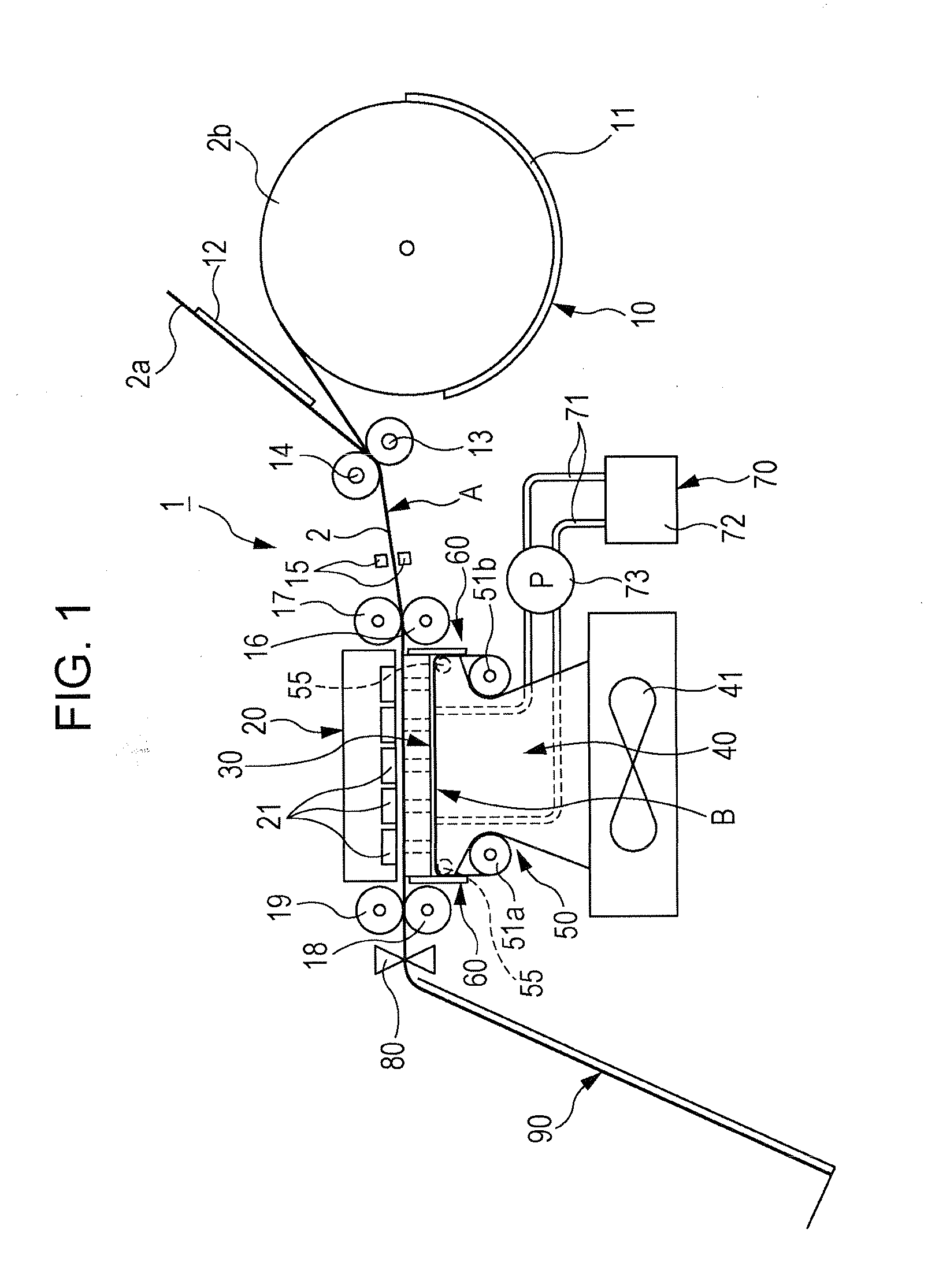
[0047](1) Overall Explanation of Recording Apparatus

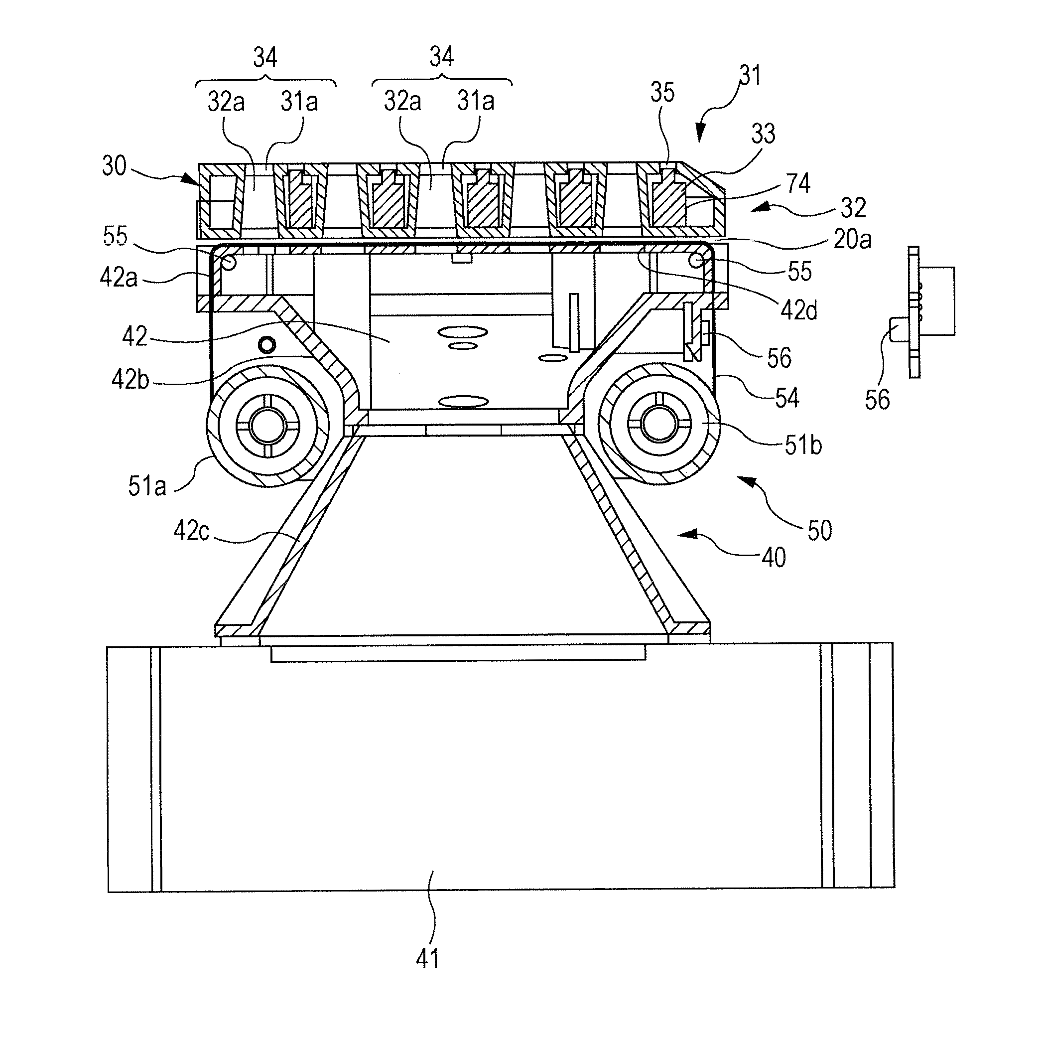
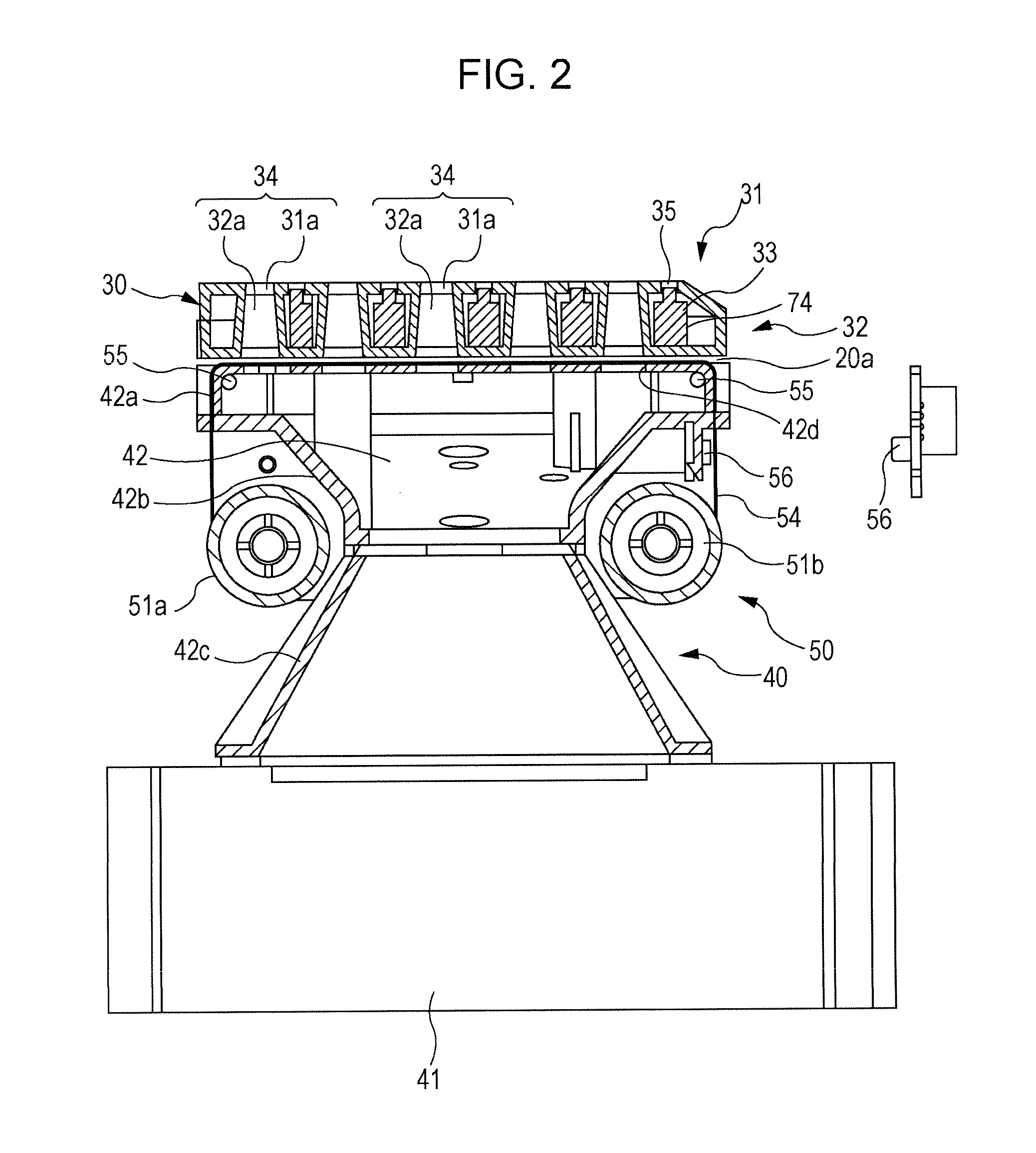
[0048](2) Explanation of Platen Section

[0049](3) Explanation of Recording Section

[0050](4) Explanation of Suction Unit

[0051](5) Explanation of Shutter Mechanism

[0052](6) Explanation of Shutter Sheet Movement Mechanism

[0053](7) Explanation of Capping Section

[0054](8) Explanation of Moisturizing Liquid Supply Section

[0055](9) Modified Example

(1) Overall Explanation of Recording Apparatus

[0056]FIG. 1 is a cross-sectional view of a line type ink jet printer apparatus 1 (hereinafter also simply referred to as a printer apparatus 1) to which the invention is applied. In FIG. 1, the printer apparatus 1 is provided with a paper feed section 10 for feeding a cut sheet 2a or a roll paper 2b, and a recording section 20 which records an image on the recording...


PUM


Abstract

A recording apparatus includes a recording head performing recording onto a recording sheet; a platen section guiding the recording sheet to a position facing the recording head; a suction unit which includes a plurality of suction openings provided at the platen section and sucks and holds the recording sheet, a suction duct provided facing the suction openings, and a suction fan connected to the suction duct, and sucks and holds the recording sheet on the platen section through the suction openings; and a shutter mechanism which opens and closes the suction duct, wherein the shutter mechanism includes a shutter sheet in which at least one exposure opening portion exposing the suction duct is formed corresponding to the width of the recording sheet, and a shutter sheet movement mechanism which makes the shutter sheet travel between the suction duct and a back surface of the platen section.

Description

BACKGROUND OF THE INVENTION[0001]1. Field of the Invention[0002]The present invention relates to a recording apparatus and a line type liquid discharge recording apparatus which are provided with a suction unit for keeping the distance between a recording sheet on a platen section and a recording head constant.[0003]2. Description of the Related Art[0004]In an ink jet recording apparatus, keeping the distance between a recording sheet on a platen and a recording head constant is an important task for performing correct impact of ink. For this reason, at the ink jet recording apparatus, a suction section which sucks the recording sheet onto an upper surface of the platen is often provided. The suction section is usually constituted by a plurality of suction openings formed in a surface of the platen and a fan which sucks external air from each suction opening.[0005]In such a configuration in which a plurality of suction openings is provided in order to suck the recording sheet onto t...

Claims


Application Information

Patent Timeline
Patent Type & Authority Applications(United States)
IPC IPC(8): B41J2/01
CPCB41J11/06B41J11/0085
Inventor MORIMOTO, TOSHIYASUKAMODA, HITOSHI
Owner SONY CORP
Why Eureka
Try Eureka