Processing apparatus

a technology of processing apparatus and separator, which is applied in the direction of grinding machine components, manufacturing tools, working accessories, etc., can solve the problems of separation processing water remaining in the separator, and achieve the effect of increasing the number of plate-like workpieces that can be processed per unit time by the processing apparatus, increasing the energy efficiency of the processing apparatus, and efficient operation

Active Publication Date: 2018-05-22
DISCO CORP
View PDF9 Cites 0 Cited by
  • Summary
  • Abstract
  • Description
  • Claims
  • Application Information

AI Technical Summary

Benefits of technology

[0007]It is, therefore, an object of the present invention to provide a processing apparatus in which a plate-like workpiece to be processed is held by a chuck table and which is capable of processing an increased number of workpieces per unit time without causing a reduction in the suction force under which the plate-like workpieces are held by the chuck table.
[0008]In accordance with an aspect of the present invention, there is provided a processing apparatus including a chuck table for holding a plate-like workpiece under suction, suction means connected to the chuck table, for causing the chuck table to generate a suction force, and processing means for processing the plate-like workpiece held by the chuck table while supplying processing water to the plate-like workpiece, wherein the suction means includes a first suction source, a first pipe providing fluid communication between the first suction source and the chuck table, a separator arranged in the first pipe, for separating a gas and a liquid drawn in from the chuck table, and water discharging means for discharging the liquid separated by the separator, and the water discharging means includes a second suction source, a second pipe providing fluid communication between the second suction source and a water discharge port of the separator, and a check valve arranged in the second pipe, for preventing a fluid from flowing from the second suction source to the separator.
[0011]With the processing apparatus according to the present invention, since the separator separates a liquid such as processing water from air drawn in by the first suction source, the suction force generated by the suction means is prevented from being lowered. As the check valve prevents a fluid from flowing from the water discharge port of the separator into the first pipe, the suction force generated by the suction means is prevented from being lowered. Furthermore, inasmuch as the liquid trapped in the separator is not drained of its own accord, but is forcibly discharged by the second suction source, the suction force generated by the suction means is prevented from being lowered. Since the liquid can be discharged from the chuck table while the plate-like workpiece held by the chuck table is being processed, it is not necessary to wait until the liquid is fully drained from the separator. Consequently, the number of plate-like workpieces that can be processed per unit time by the processing apparatus can be increased.
[0012]If the amount of liquid trapped in the separator exceeds the predetermined amount, then the second suction source is actuated, and if the liquid trapped in the separator is fully discharged, then the second suction source is shut down. Since the second suction source is thus efficiently operated, the energy efficiency of the processing apparatus is increased.

Problems solved by technology

However, if the water discharge port is closed, then the separated processing water remains trapped in the separator.

Method used


Image

  • Processing apparatus
  • Processing apparatus
  • Processing apparatus

Examples


Embodiment Construction

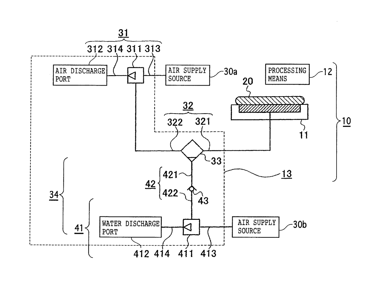
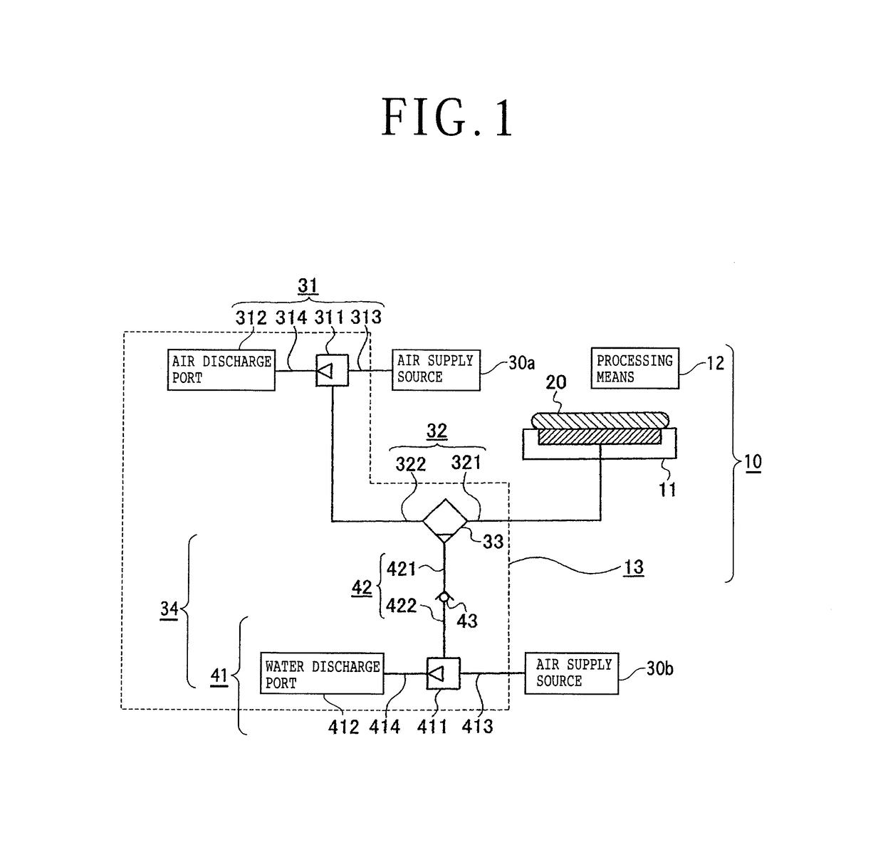
[0017]FIG. 1 shows a processing apparatus 10 according to an embodiment of the present invention. The processing apparatus 10 is an apparatus for processing, e.g., cutting, grinding, or polishing, a plate-like workpiece 20. The processing apparatus 10 includes a chuck table 11 for holding the plate-like workpiece 20 under suction, suction means 13 connected to the chuck table 11, and processing means 12 for processing the plate-like workpiece 20 that is held by the chuck table 11. The processing means 12 includes, for example, cutting means for forcing a cutting blade having a cutting wheel (cutter) into the plate-like workpiece 20 to cut the plate-like workpiece 20. The processing means 12 uses processing water to cool the cutting wheel and processes the plate-like workpiece 20 while supplying the processing water to the plate-like workpiece 20.

[0018]The suction means 13 serves to draw in air from the chuck table 11 to cause the chuck table 11 to generate a suction force. The sucti...


PUM

PropertyMeasurementUnit
suction forceaaaaaaaaaa
pressureaaaaaaaaaa
energy efficiencyaaaaaaaaaa

Abstract

A processing apparatus includes a chuck table for holding a plate-like workpiece under suction. A suction unit is connected to the chuck table, and a processing unit is configured to process the workpiece while supplying processing water to the workpiece. The suction unit includes a first suction source, a first pipe providing fluid communication between the first suction source and the chuck table, a separator arranged in the first pipe, for separating a gas and a liquid drawn in from the chuck table, and a water discharging unit configured to discharge the liquid separated by the separator. The water discharging unit includes a second suction source, a second pipe providing fluid communication between the second suction source and a water discharge port of the separator, and a check valve arranged in the second pipe, for preventing a fluid from flowing from the second suction source to the separator.

Description

BACKGROUND OF THE INVENTION[0001]Field of the Invention[0002]The present invention relates to a processing apparatus for processing a plate-like workpiece held under suction by a chuck table while supplying processing water to the planar workpiece.[0003]Description of the Related Art[0004]Cutting apparatus for rotating a cutting blade and forcing the cutting blade into a plate-like workpiece such as a semiconductor wafer or the like to cut the plate-like workpiece use a chuck table for holding the plate-like workpiece under suction. The chuck table employs, as a suction source, an ejector for attracting the plate-like workpiece under a negative pressure that is developed when air flows (see, for example, Re-publication of PCT International Publication No. 2005-3043).[0005]Processing apparatus that process a workpiece with a grinding wheel such as a cutting blade or the like, as is the case with the above cutting apparatus, use processing water for cooling the grinding wheel. During ...

Claims


Application Information

Patent Timeline
Patent Type & Authority Patents(United States)
IPC IPC(8): B25B11/00B24B27/06B24B55/02B28D7/04
CPCB28D7/046B24B55/02B24B27/0683B28D5/0076B28D5/0094B25B11/005H01L21/6838H01L21/67017H01L21/67253B24B41/068B24B49/08B24B55/03
Inventor NAGAO, RYOSUKE
Owner DISCO CORP
Why Eureka
Try Eureka