Stereoscopic-image display device
- Summary
- Abstract
- Description
- Claims
- Application Information
AI Technical Summary
Problems solved by technology
Method used
Image
Examples
first embodiment
[0045](Configuration of a Stereoscopic-Image Display System)
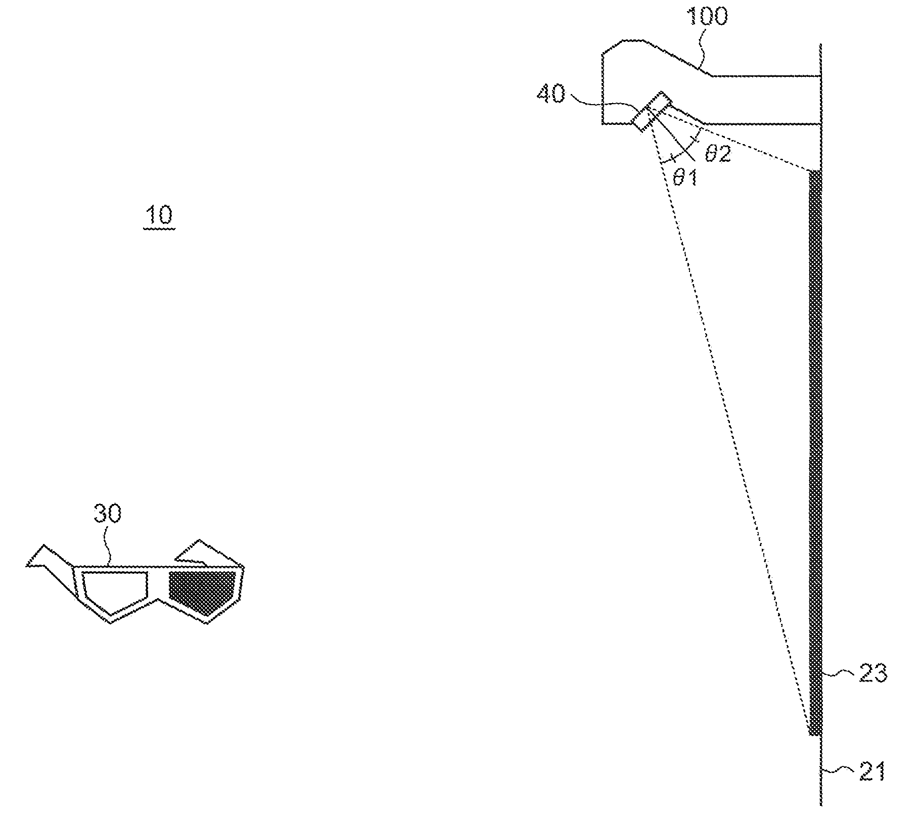
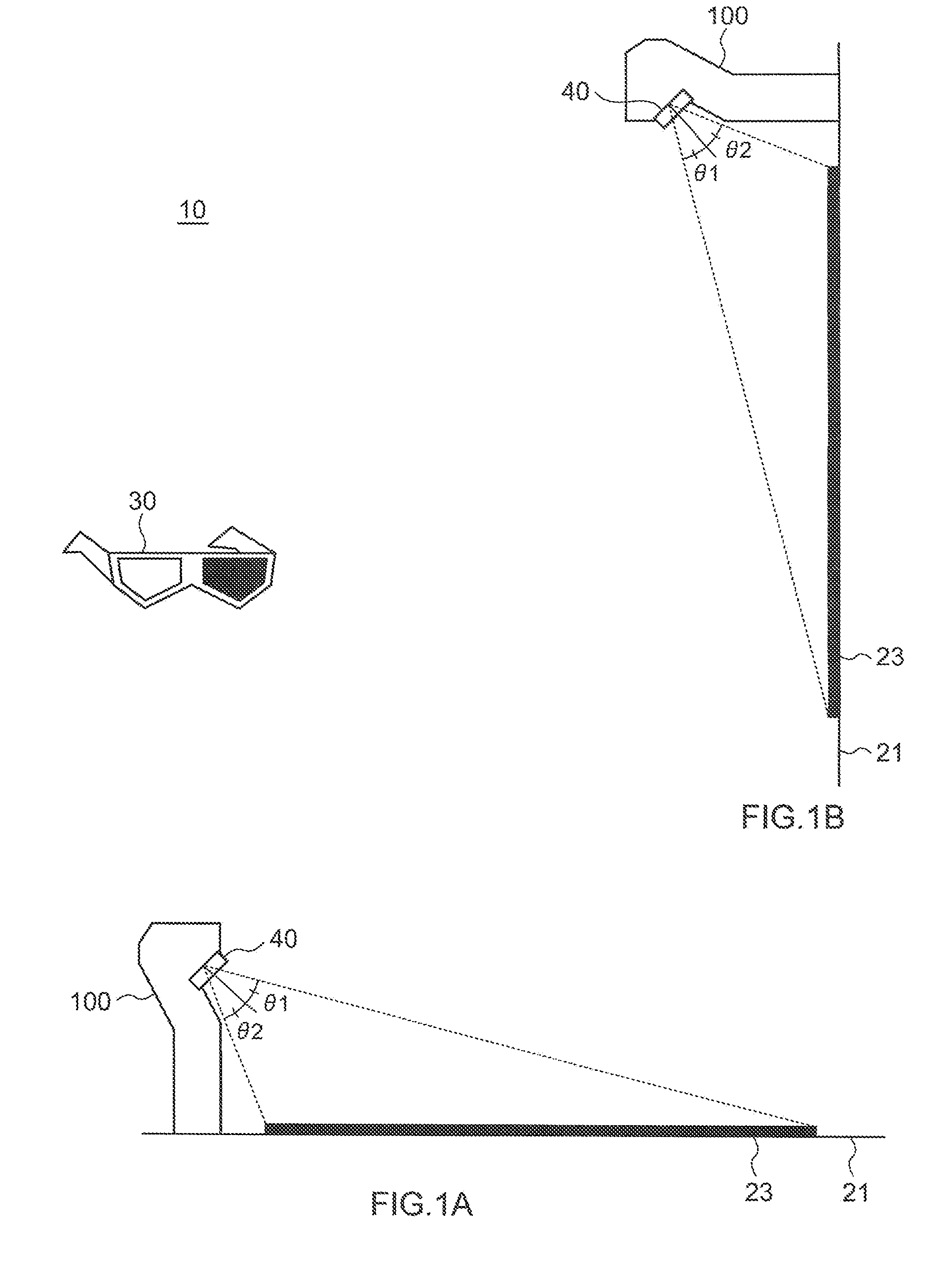
[0046]FIG. 1 is a diagram illustrating the configuration of a stereoscopic-image display system 10 according to a first embodiment of the present invention. The stereoscopic-image display system 10 is provided with a projection-type video-image display device 100, a camera (not shown) provided being adjacent to or incorporated in the projection-type video-image display device, a screen 21, and glasses 30.
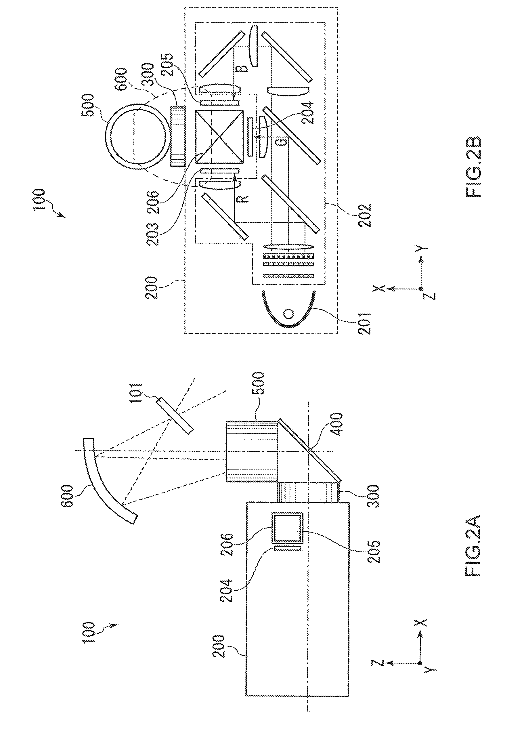
[0047]The projection-type video-image display device 100, which functions as an image display unit, is so-called an ultra-short focus projector that can be placed in an extremely short distance from a projection plane such as a screen. As shown in FIG. 1A, the projection-type video-image display device 100 of the present embodiment is placed on a floor and projects an image onto a display area 23 on a screen 21, which is also placed on the floor. Alternately, as shown in FIG. 1B, the projection-type video-image display devi...
second embodiment
[0101]The second embodiment of the present invention is now described in detail.
[0102]In general, the correspondence relationship between each image and the position of a viewpoint can become unclear since a stereoscopic image includes an image for a left eye and an image for a right eye, that is, images with two viewpoints. When the image for a left eye and the image for a right eye are reproduced in an incorrect order, the observer may see a stereoscopic image that is inverted from its correct state or may not be able to see a stereoscopic image very well. This is called pseudoscopic perception. In other words, pseudoscopic perception is a state where the right eye sees the image for a left eye and the left eye sees the image for a right eye.
[0103]In the state of pseudoscopic perception, a correct stereoscopic effect cannot be obtained. For this reason, there exists a product with a projector or shutter glasses, which is provided with a reverse button for the display order of imag...
third embodiment
[0169]The third embodiment of the present invention is now described in detail.
[0170]In a method where two kinds of images having predetermined parallax are displayed in a time-divided or space-divided manner, a position of observation at which a stereoscopic image can be perceived may be limited. In other words, when a stereoscopic image is observed from the direction in which there is no binocular parallax produced, the stereoscopic image cannot be perceived as a stereoscopic image. For example, when a stereoscopic image is displayed on the floor and when two kinds of images are displayed such that parallax is produced being viewed from the direction of a given side of a display surface, the stereoscopic image can be perceived as a stereoscopic image from the direction but cannot be perceived as a stereoscopic image from a direction of a different side.
[0171]In the third embodiment, a technique that allows a user to observe a stereoscopic image from a position of observation at wh...
PUM
 Abstract
Description
Claims
Application Information
 - R&D
- Intellectual Property
- Life Sciences
- Materials
- Tech Scout
- Unparalleled Data Quality
- Higher Quality Content
- 60% Fewer Hallucinations
Browse by: Latest US Patents, China's latest patents, Technical Efficacy Thesaurus, Application Domain, Technology Topic, Popular Technical Reports.
© 2025 PatSnap. All rights reserved.Legal|Privacy policy|Modern Slavery Act Transparency Statement|Sitemap|About US| Contact US: help@patsnap.com


