
Wire harness and method of manufacturing the same

Inactive Publication Date: 2011-06-30
HITACHI CABLE
View PDF3 Cites 10 Cited by
  • Summary
  • Abstract
  • Description
  • Claims
  • Application Information

AI Technical Summary

Benefits of technology

[0015]Therefore, it is an object of the invention to provide a wire harness that is capable of sufficiently maintaining air-tightness between a housing of a connector and a cable without melting a sheath of the cable as much as possible and a method of manufacturing the wire harness.

Problems solved by technology

However, the above-mentioned wire harness 121 has a problem described below.

Method used


Image

  • Wire harness and method of manufacturing the same
  • Wire harness and method of manufacturing the same
  • Wire harness and method of manufacturing the same

Examples


Embodiment Construction

[0070]The preferred embodiments according to the invention will be explained below referring to the drawings.

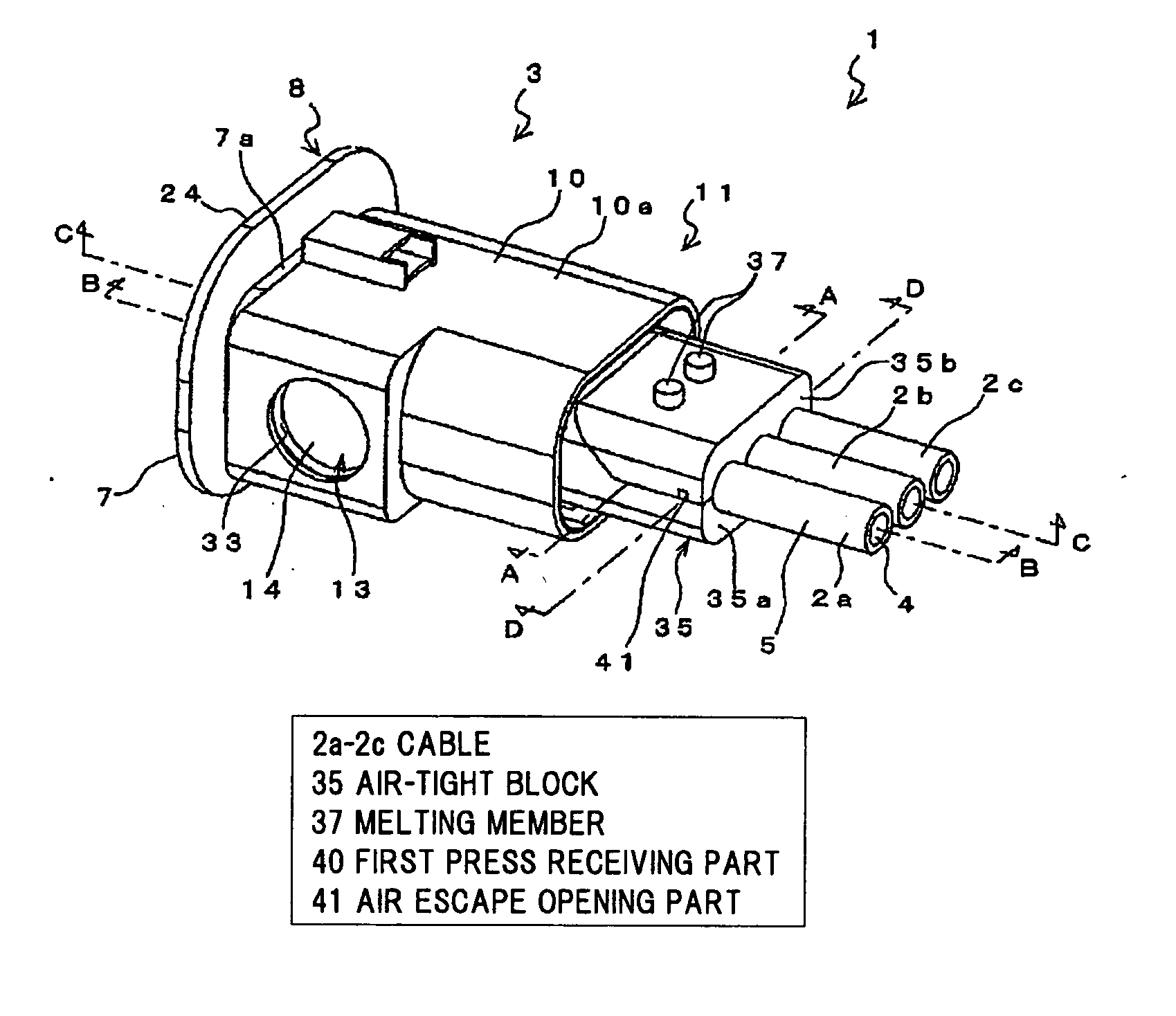
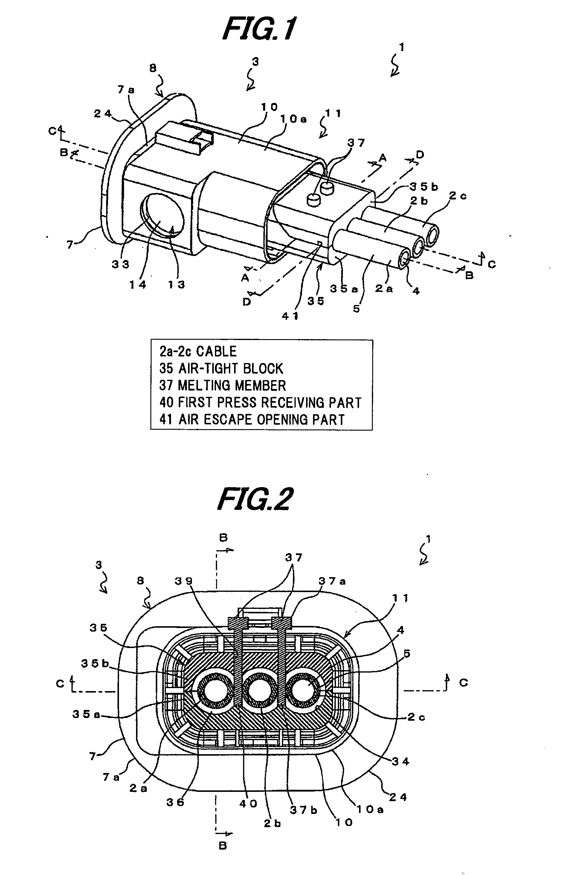
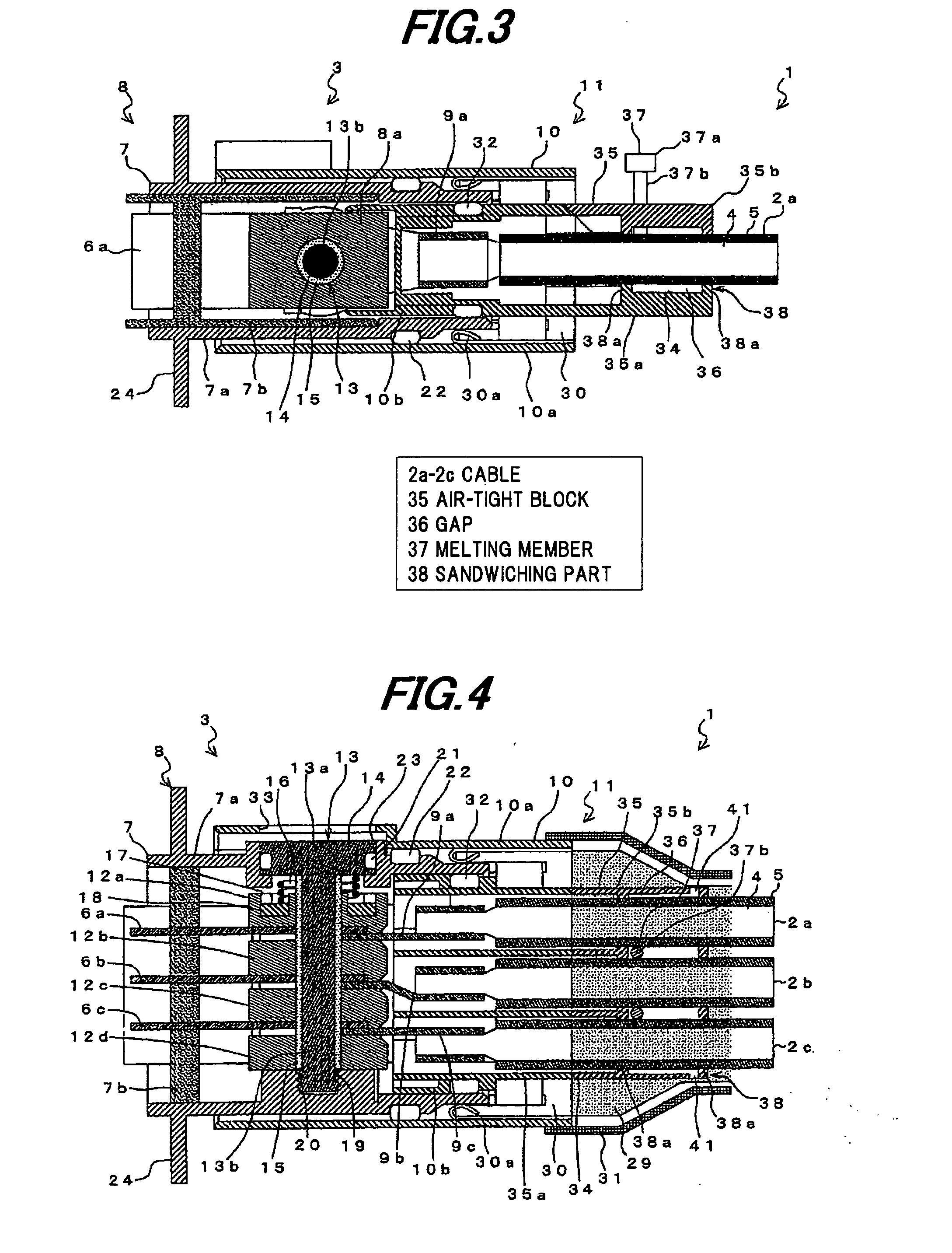
[0071]FIG. 1 is a perspective view schematically showing a wire harness according to one embodiment of the invention, FIG. 2 is a cross-sectional view taken along the line A-A in FIG. 1, FIG. 3 is a cross-sectional view taken along the line B-B in FIG. 1, FIG. 4 is a cross-sectional view taken along the line C-C in FIG. 1, and FIG. 5 is a cross-sectional view taken along the line D-D in FIG. 1. Further, the detail will be explained later, but FIG. 1 shows a state after a melting member 37 is melted and FIGS. 2 to 5 show a state before the melting member 37 is melted.

[0072]As shown in FIGS. 1 to 5, a wire harness 1 includes a plurality of cables 2a to 2c arranged in parallel and a connector 3 to which end portions of the cables 2a to 2c are connected.

[0073]The wire harness 1 is used for, for example, a connection between a motor of a hybrid electric vehicle (HEV) and an invert...


PUM

PropertyMeasurementUnit
Distanceaaaaaaaaaa
Melting pointaaaaaaaaaa

Abstract

A wire harness includes a plurality of cables arranged in parallel, and a connector including a housing to which end portions of the plurality of cables are connected. An air-tight block includes two closing parts, an insertion part, a press receiving part, and an air escape opening part that opens from a cable insertion hole between the closing parts toward an outside of the air-tight block. Air-tightness between the air-tight block and the cables is maintained by a first step that a melting member is vibrated and pressed to the press receiving part to have a melt resin, which is poured into a gap between the closing parts, and a periphery of the cables is covered with the melt resin, a second step that the air escape opening part is closed, and a third step that the cables are pressed by the melt resin poured into the gap.

Description

[0001]The present application is based on Japanese patent application No. 2009-293346 filed on Dec. 24, 2009, the entire contents of which are incorporated herein by reference.BACKGROUND OF THE INVENTION[0002]1. Field of the Invention[0003]This invention relates to a wire harness that is capable of sufficiently maintaining air-tightness between a housing of a connector and a cable and a method of manufacturing the wire harness.[0004]2. Description of the Related Art[0005]Generally, in a wire harness used for vehicles etc., a water proof structure is installed between the housing of the connector and the cable in order to prevent water or the like from entering into the inside of the connector so as to cause a problem.[0006]A conventional wire harness 111 shown in FIGS. 17A and 17B uses a wire seal 114 as the air-tightness maintaining structure.[0007]The wire harness 111 is configured to maintain the air-tightness between the outer housing 113 of the connector 116 and the cable 112 b...

Claims


Application Information

Patent Timeline
IPC IPC(8): H01R13/52B29C35/02
CPCH01R13/504Y10S439/936H01R13/621H01R13/5205
Inventor SUZUKI, SACHIOTAKEHARA, HIDEAKIFUKUDA, KUNIHIROKATAOKA, YUTAHAYASHI, SHINYA
Owner HITACHI CABLE
Learn More