Wiper blade

Active Publication Date: 2011-07-07
DENSO CORP
View PDF15 Cites 91 Cited by
  • Summary
  • Abstract
  • Description
  • Claims
  • Application Information

AI Technical Summary

Problems solved by technology

As a result, there is a tendency for contact friction or the like of the rubber blade and the wiping surface causing chatter vibration.
Thus, a small rattling near the pivot shaft of the movable cover member results in a large rattling in the wiping direction at the distal portion.
Accordingly, a large deflection at the follow

Method used


Image

  • Wiper blade
  • Wiper blade
  • Wiper blade

Examples


Embodiment Construction

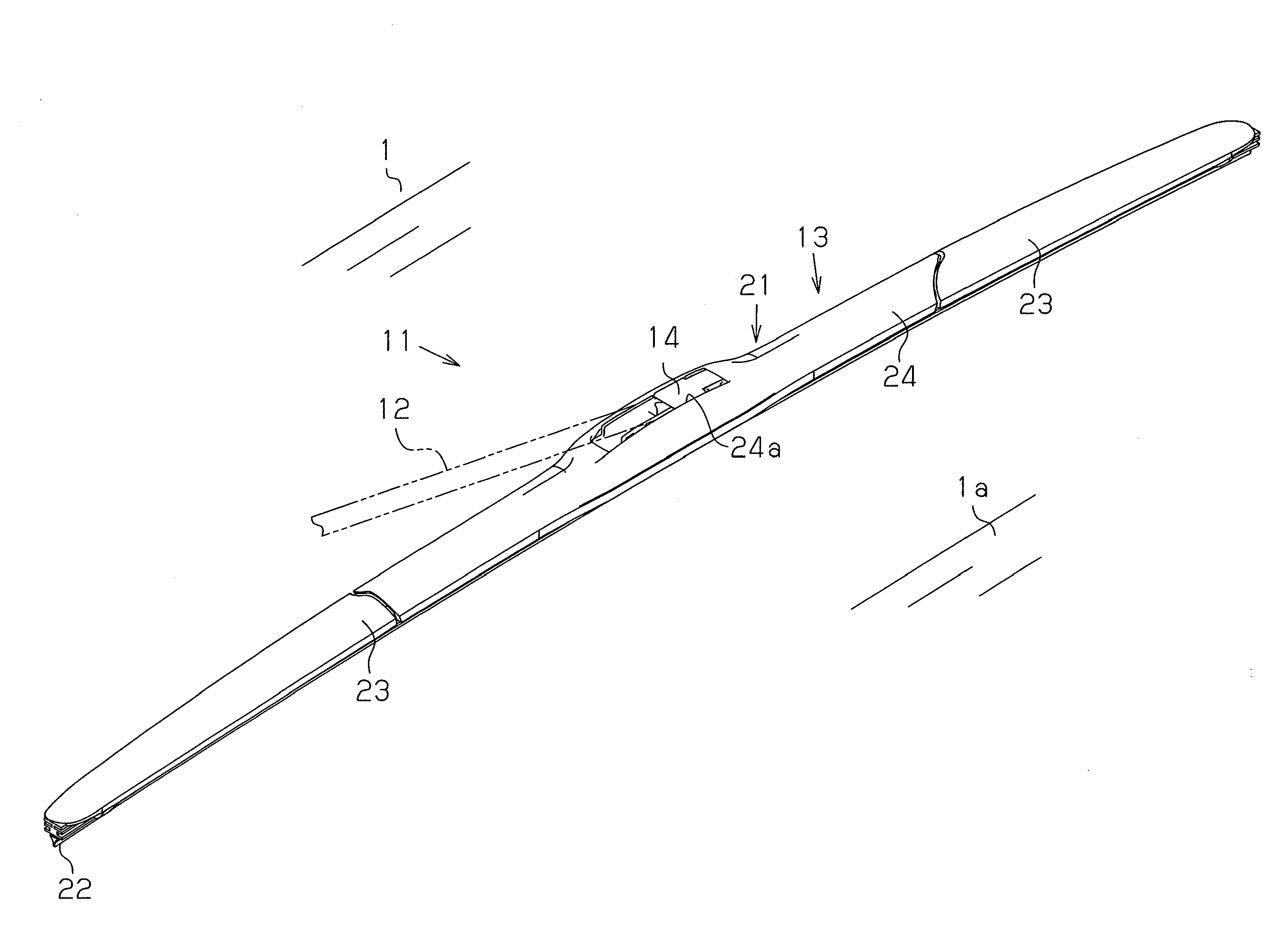
[0033]One embodiment of the present invention will now be discussed with reference to FIGS. 1 to 5.

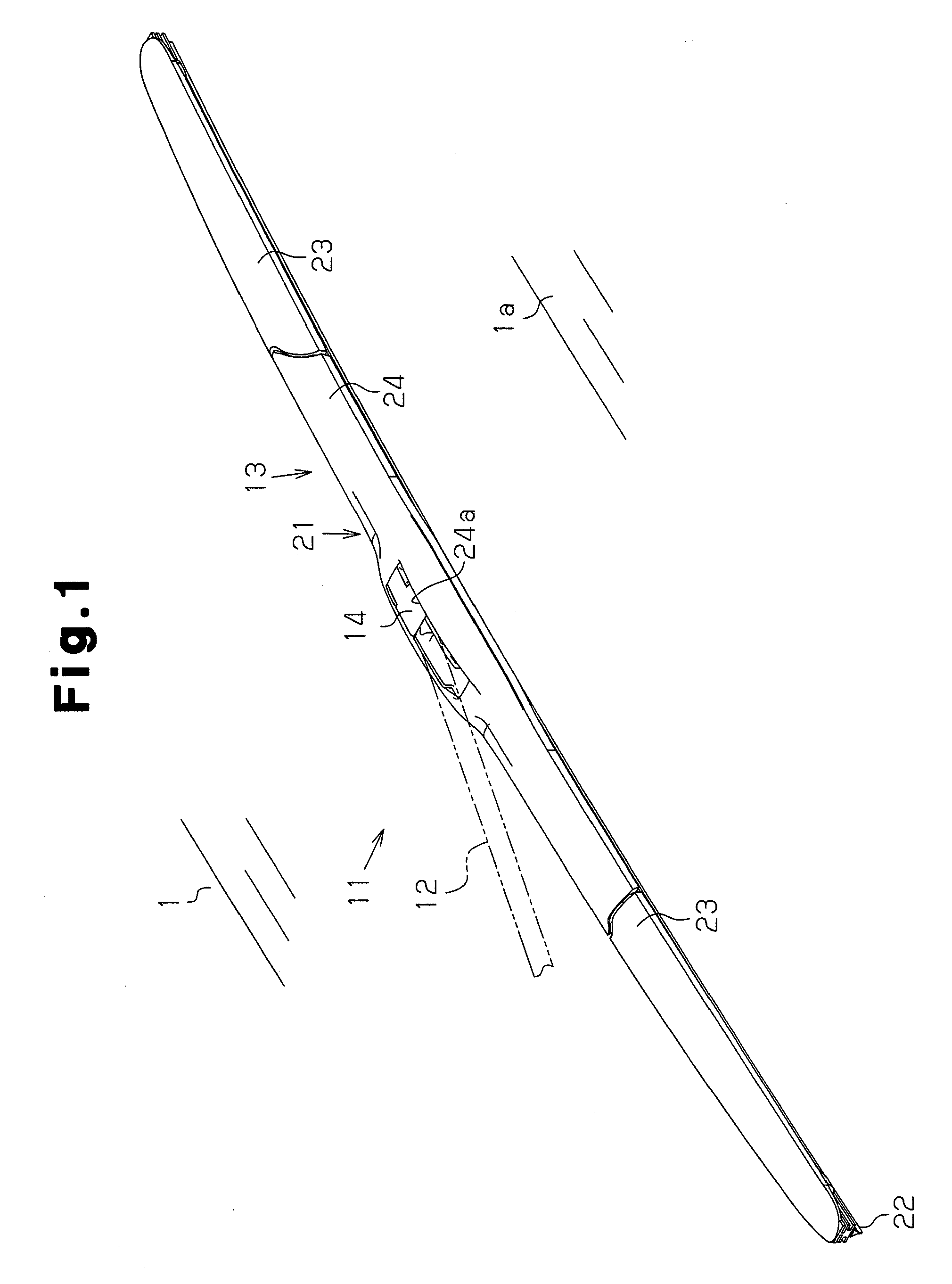
[0034]FIG. 1 shows a vehicle wiper 11 for wiping raindrops or the like on a wiping surface 1a of a windshield (windshield glass) 1 for an automobile. The wiper 11 includes a wiper arm 12 and a wiper blade 13. The wiper arm 12 has a basal portion fixed to a pivot shaft (not shown) that is rotated back and fourth within a predetermined rotational angular range by the driving force of a wiper motor (not shown). The wiper arm 12 swings back and fourth when the pivot shaft rotates back and fourth. A coupling clip 14 pivotally couples the wiper blade 13 to a distal portion of the wiper arm 12. A spring (not shown), which applies a pushing force for pushing the wiper blade 13 against the wiping surface la, is attached to the wiper arm 12.

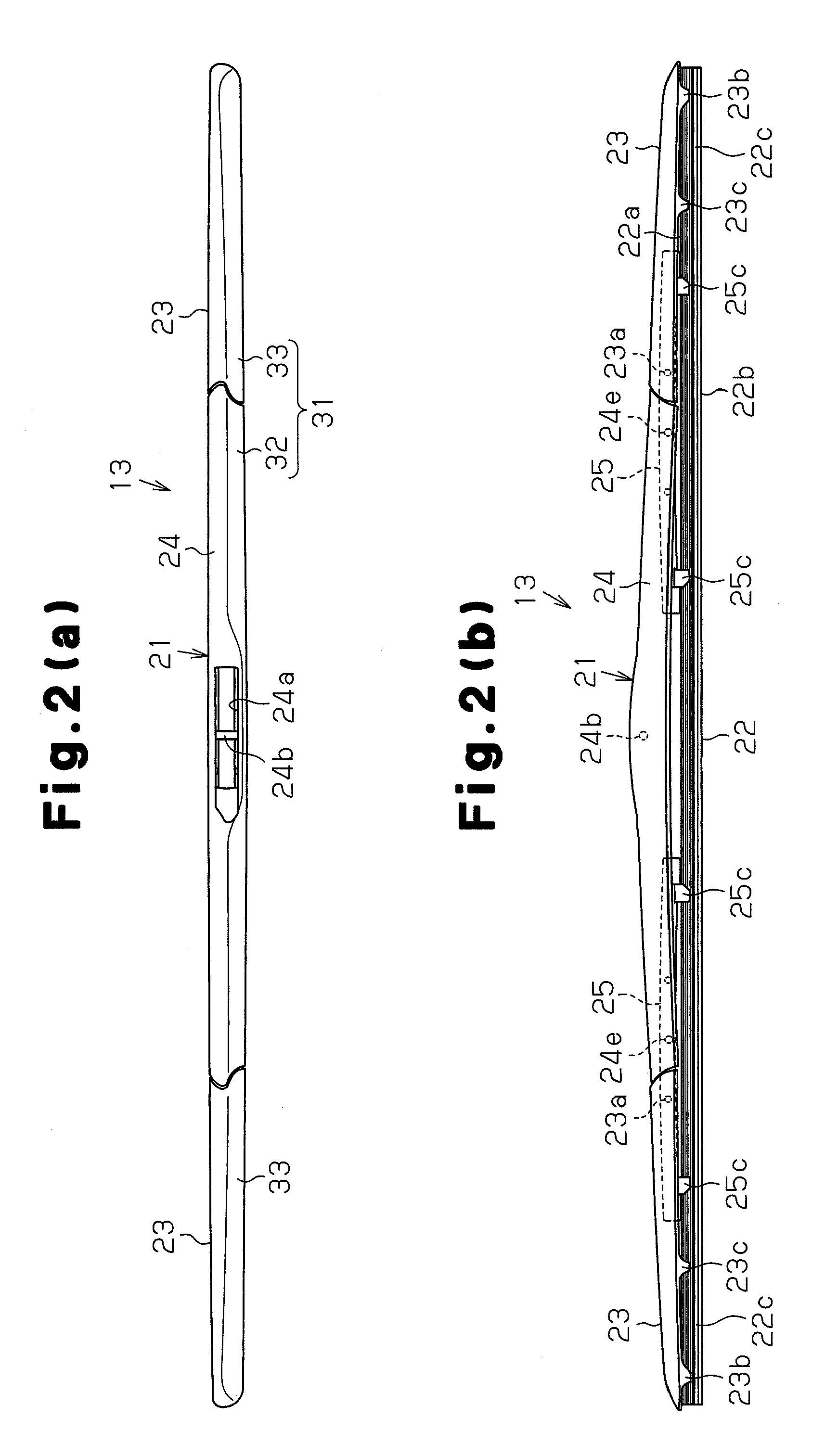
[0035]As shown in FIGS. 2(a) to 3, the wiper blade 13 includes a lever member 21, a rubber blade 22, and two movable cover members 23. In FIGS. 2(a) to 3, th...


PUM


Abstract

A wiper blade including a lever member, a rubber blade, and a movable cover member is disclosed. The lever member includes a main lever and a yoke lever. The main lever is coupled to a wiper arm. The yoke lever is coupled to the main lever. The yoke lever includes a plurality of grip portions. The rubber blade is gripped by the plurality of grip portions to wipe a wiping surface. The rubber blade includes a following end projecting outward from the one of the grip portions that is located at a longitudinally outer side of the lever member. The movable cover member covers at least part of the yoke lever. The movable cover member includes a holding portion and a basal portion. The holding portion holds the following end. The basal portion is pivotally coupled to the yoke lever so that the movable cover member pivots relative to the yoke lever when the following end bends and deforms in a direction orthogonal to the wiping surface.

Description

TECHNICAL FIELD[0001]The present invention relates to a wiper blade suitable for wiping a windshield surface or the like of an automobile.BACKGROUND ART[0002]A wiper device arranged in a vehicle includes a wiper blade coupled to a wiper arm. One example of such a known wiper blade is provided with a cover that covers a lever assembly including a yoke lever to improve the wiping performance when the vehicle is traveling and improve the outer appearance (aesthetic appeal). An example of such a cover for a wiper blade is disclosed in patent document 1 in which a movable cover member is pivotal to a main lever (primary lever) of the wiper blade. The movable cover member has a basal end pivotally coupled to the main lever. The movable cover member extends to cover part of the yoke lever. Further, the movable cover member has a distal portion that holds a following end of a rubber blade, which projects from a grip portion of the yoke lever in a longitudinal direction. The movable cover me...

Claims


Application Information

Patent Timeline
IPC IPC(8): B60S1/38
CPCB60S1/3801B60S2001/3815B60S1/3806
Inventor AMADO, SHINICHIROU
Owner DENSO CORP
Why Eureka
Try Eureka