Load Control Device Having A Visual Indication of Energy Savings and Usage Information

a technology of energy saving and usage information, applied in the direction of process and machine control, horology, instruments, etc., can solve problems such as energy was

Active Publication Date: 2011-07-07
LUTRON TECH CO LLC
View PDF27 Cites 56 Cited by
  • Summary
  • Abstract
  • Description
  • Claims
  • Application Information

AI Technical Summary

Problems solved by technology

However, many users of dimmer switches unintentionally control the intensity of the lighting load to a level that is higher than actually needed, i.e., to a level that provides more light than is needed, thus, wasting energy.

Method used


Image

  • Load Control Device Having A Visual Indication of Energy Savings and Usage Information
  • Load Control Device Having A Visual Indication of Energy Savings and Usage Information
  • Load Control Device Having A Visual Indication of Energy Savings and Usage Information

Examples


first embodiment

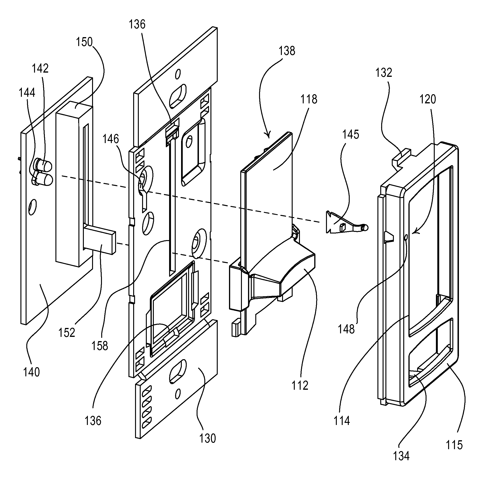
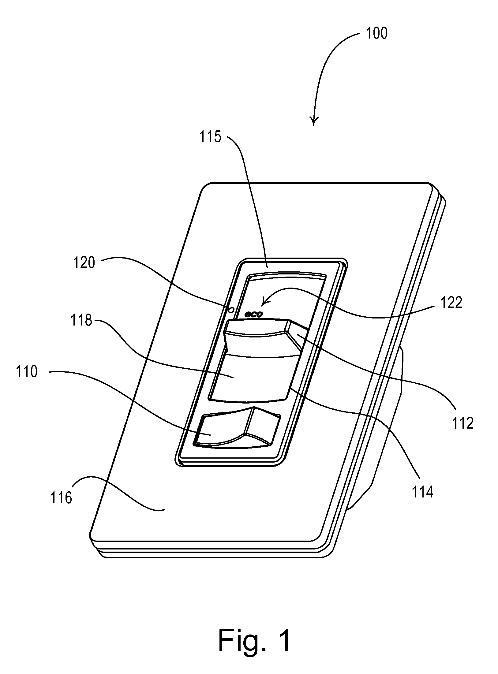
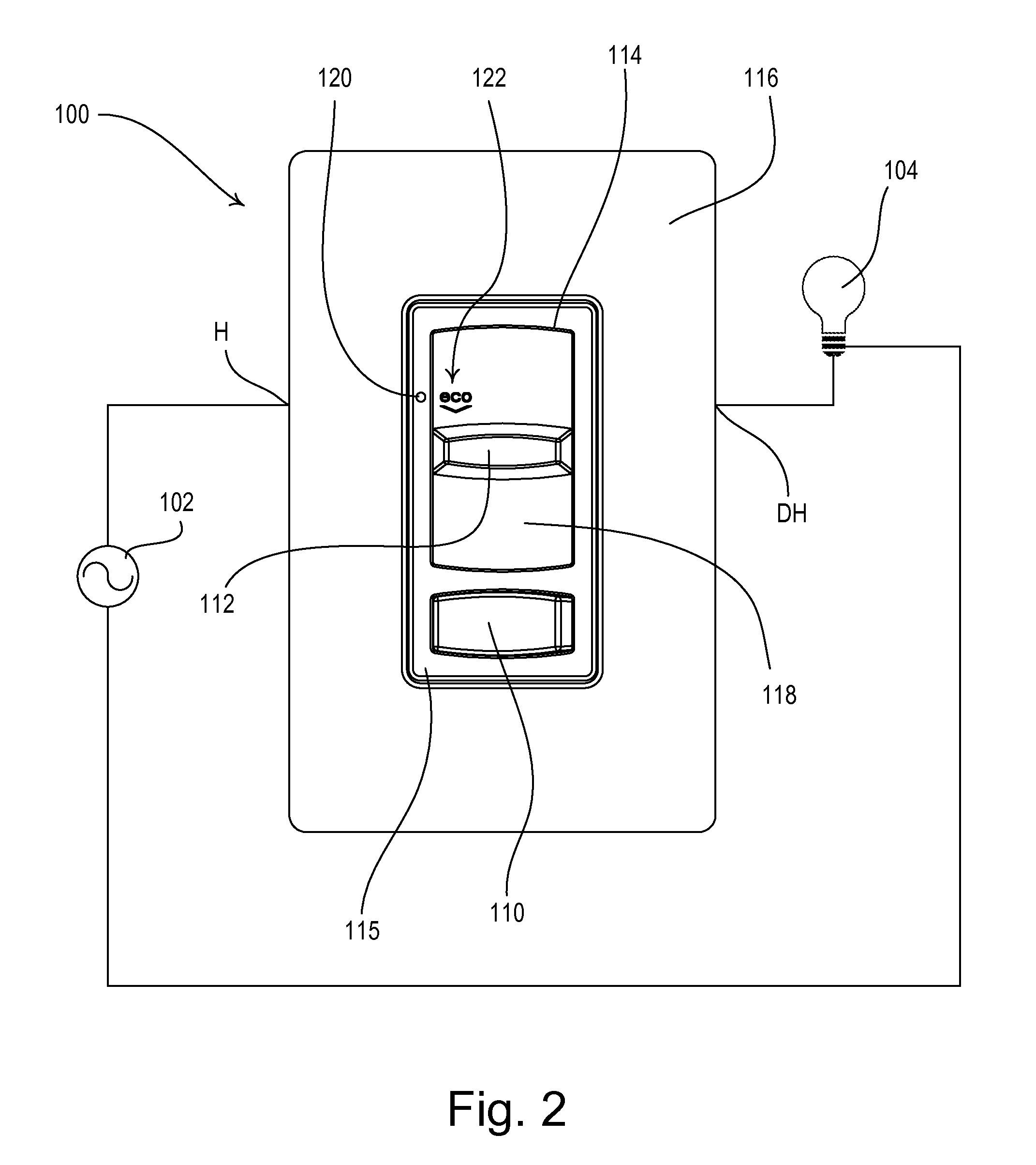
[0044]FIG. 1 is a perspective view of a dimmer switch 100 that provides a visual indication of energy savings and usage information according to the present invention. FIG. 2 shows a front view of the dimmer switch 100, which is coupled in series electrical connection between an alternating-current (AC) power source 102 and a lighting load 104 for control of the amount of power delivered to the lighting load. The dimmer switch 100 is coupled to the power source 102 via a hot terminal H and to the lighting load 104 via a dimmed hot terminal DH. Accordingly, the dimmer switch 100 is operable to turn the lighting load 104 on and off and to control a present lighting intensity L (i.e., a perceived lighting intensity) of the lighting load across a dimming range between a low-end lighting intensity LLE (e.g., approximately 5% of a maximum possible intensity LMAX) and a high-end lighting intensity LHE (e.g., approximately 92% of the maximum possible intensity LMAX). The maximum possible in...

second embodiment

[0062]FIG. 7A is a front view and FIG. 7B is a right-side view of a slide-to-off dimmer switch 200 for providing a visual indication representative of energy savings and usage information according to the present invention. The dimmer switch 200 comprises a slider knob 210 adapted to slide along the length of an opening 214 of a faceplate 216. Adjustment of the slider knob 210 causes the dimmer switch 200 to adjust the amount of power delivered to the connected lighting load 104 and thus the intensity of the lighting load. When the slider knob 210 is adjusted to the lowermost position, the slider knob is operable to actuate the mechanical switch S20 to open the mechanical switch S20, such that the dimmer switch 200 turns off the connected lighting load 104. Alternatively, the dimmer switch 200 could comprise a toggle actuator (not shown) that is positioned in the middle of the slider knob 210 and is coupled to the mechanical switch S20 for turning the lighting load 104 on and off, a...

third embodiment

[0064]FIG. 8 is a front view of a traditional-opening dimmer switch 200′ for providing a visual indication representative of energy savings and usage information according to the present invention. The dimmer switch 200′ comprises a toggle actuator, such as a standard toggle switch or a rectangular pushbutton 210′ (as shown in FIG. 8). The dimmer switch 200′ also comprises an intensity adjustment actuator, such as a slider knob 212′, which is adapted to slide along the length of an elongated slider slot 214′ of a frame 215′. As shown in FIG. 8, the rectangular pushbutton 210′, the slider knob 212′, the slider slot 214′, and the frame 215′ are all provided in an opening of a traditional-style faceplate 216′. The pushbutton 210′ is supported for inward translation with respect to the frame 215′ in a sliding manner. Consecutive presses of the pushbutton 210′ toggle the connected lighting load 104 on and off. Adjustment of the slider knob 212′ along the slider slot 214′ causes the dimme...


PUM


Abstract

A dimmer switch for controlling the amount of power delivered to and thus the intensity of a lighting load comprises a visual display operable to provide a visual indication representative of energy savings and usage information. The dimmer switch comprises an intensity adjustment actuator, such as a slider knob or a rotary knob, which may be coupled to a potentiometer for adjusting the amount of power delivered to the lighting load. The potentiometer may comprise a dual potentiometer including a resistive element and a conductive element having a cut. The visual display may comprise a single visual indicator, which may be illuminated a first color, such as green, when the intensity of the lighting load is less than or equal to the eco-level intensity, and illuminated a second different color, such as red, when the intensity of the lighting load is greater than the eco-level intensity.

Description

RELATED APPLICATIONS[0001]This application is a continuation-in-part application of commonly-assigned, U.S. patent application Ser. No. 12 / 363,258, filed Jan. 30, 2009, entitled LOAD CONTROL DEVICE HAVING A VISUAL INDICATION OF ENERGY SAVINGS AND USAGE INFORMATION, which is a non-provisional application of commonly-assigned U.S. Provisional Application Ser. No. 61 / 117,624, filed Nov. 25, 2008, entitled LOAD CONTROL DEVICE THAT PROVIDES A VISUAL INDICATION OF ENERGY SAVING INFORMATION, and U.S. Provisional Application Ser. No. 61 / 139,206, filed Dec. 19, 2008, entitled LOAD CONTROL DEVICE PROVIDING A VISUAL INDICATION OF ENERGY USAGE INFORMATION, the entire disclosures of which are hereby incorporated by reference.BACKGROUND OF THE INVENTION[0002]1. Field of the Invention[0003]The present invention relates to a load control device for controlling the amount of power delivered to an electrical load, and more particularly, to a dimmer switch having a visual display, such as a single vis...

Claims


Application Information

Patent Timeline
Patent Type & Authority Applications(United States)
IPC IPC(8): G04F3/06H01H9/00
CPCH01H9/181H01H15/025H05B37/02H05B39/085H01H2231/052H05B47/10H05B47/165Y02B20/40H01H13/023
Inventor ALTONEN, GREGORYJACOBY, ELLIOT G.SALVESTRINI, CHRISTOPHER JAMESSTEFFIE, JAMIE J.SPIRA, JOEL S.
Owner LUTRON TECH CO LLC
Why Eureka
Try Eureka