Eureka AIR delivers breakthrough ideas for toughest innovation challenges, trusted by R&D personnel around the world.

Cutting pick and mounting assembly

Inactive Publication Date: 2011-07-07
SANDVIK INTELLECTUAL PROPERTY AB
View PDF4 Cites 8 Cited by
  • Summary
  • Abstract
  • Description
  • Claims
  • Application Information

AI Technical Summary

Benefits of technology

[0008]The arrangement between the shank, the inner sleeve, the outer sleeve and the mounting hole is such that upon the cutting pick being subjected to a load which tends to cause movement of the cutting pick relative to the mounting hole, that movement can cause movement of the inner sleeve relative to the outer sleeve. Movement of the cutting pick and the cutting pick shank relative to the mounting hole can cause movement of the inner sleeve relative to the outer sleeve, whereby either or both of the sleeves can wear sacrificially instead of the cutting pick, the shank of the cutting pick and / or the cutting pick mounting hole. Consequently, an advantage of the invention is that wear of the cutting pick mounting hole and / or the cutting pick or the shank of the cutting pick upon movement of the cutting pick and the shank of the cutting pick relative to the mounting hole can be reduced.
[0009]In one form, the outer sleeve remains substantially stationary relative to the cutting pick mounting hole such that in use when the cutting pick engages an earth face, any axial or lateral movement of the cutting pick relative to the mounting hole results in sacrificial wearing of the inner sleeve and / or the outer sleeve rather than wear occurring in the shank of the cutting pick or the surface of the cutting pick mounting hole.
[0010]One purpose of sacrificial wearing of the inner sleeve and / or the outer sleeve is to reduce or eliminate the amount of wear encountered by parts of the cutting pick which would normally encounter wear as a result of relative movement of the cutting pick and the mounting hole and in particular the shank of the cutting pick. Another purpose is to reduce the amount of wear encountered in sections of the cutting pick mounting hole which would normally wear as a result of relative movement of the cutting pick and the mounting hole. Thus, the above arrangement is particularly advantageous in extending the useful life of the cutting pick and the cutting pick mounting hole and in turn the useable life of the cutting assembly, such as a cutter support and a rotary cutter or any other form of cutter, or of a piece of mining or excavation equipment incorporating one or more of the cutting pick and mounting assemblies disclosed herein.
[0011]Another advantage of the cutting pick and mounting assemblies disclosed herein is that the outer sleeve can be used to fill a gap between a radially outwardly facing surface of the shaft of the inner sleeve and the facing surface of the cutting pick mounting hole which may result over time due to wearing of the surface of the cutting pick mounting hole. As the gap becomes larger then outer sleeves of greater thicknesses can be used to fill or take up the gap.
[0012]In one form, the outer sleeve is a substantially annular member having an inner surface that defines the inner sleeve opening and that is configured to face a facing surface of the inner sleeve. The outer sleeve can also have an outer surface that is configured for face to face contact with a facing surface of the cutting pick mounting hole.
[0013]The outer sleeve can include at least one hole extending partially or fully between the inner surface and the outer surface for facilitating the removal of the outer sleeve either from around the inner sleeve or from within the cutting pick mounting hole, such as by a suitable tool that engages the hole.

Problems solved by technology

This action results in a significant amount of force being translated through the cutting tip and the shank of the cutting pick into the cutting pick mounting hole of the rotating drum.
Furthermore, the cutting pick usually is rotatably mounted within the mounting hole to permit the pick to wear more evenly, but movement of pick within the mounting hole is such that over time the shank of the cutting pick and / or the surface of the mounting hole can wear.
Over time the wear may be extensive and result in the shank of the cutting pick being worn to the extent that the shank may break or alternatively the surface of the mounting hole may wear to the extent that it may no longer effectively be able to retain the shank of the cutting pick therewithin.
In one form, the outer sleeve remains substantially stationary relative to the cutting pick mounting hole such that in use when the cutting pick engages an earth face, any axial or lateral movement of the cutting pick relative to the mounting hole results in sacrificial wearing of the inner sleeve and / or the outer sleeve rather than wear occurring in the shank of the cutting pick or the surface of the cutting pick mounting hole.

Method used


Image

  • Cutting pick and mounting assembly
  • Cutting pick and mounting assembly
  • Cutting pick and mounting assembly

Examples


Embodiment Construction

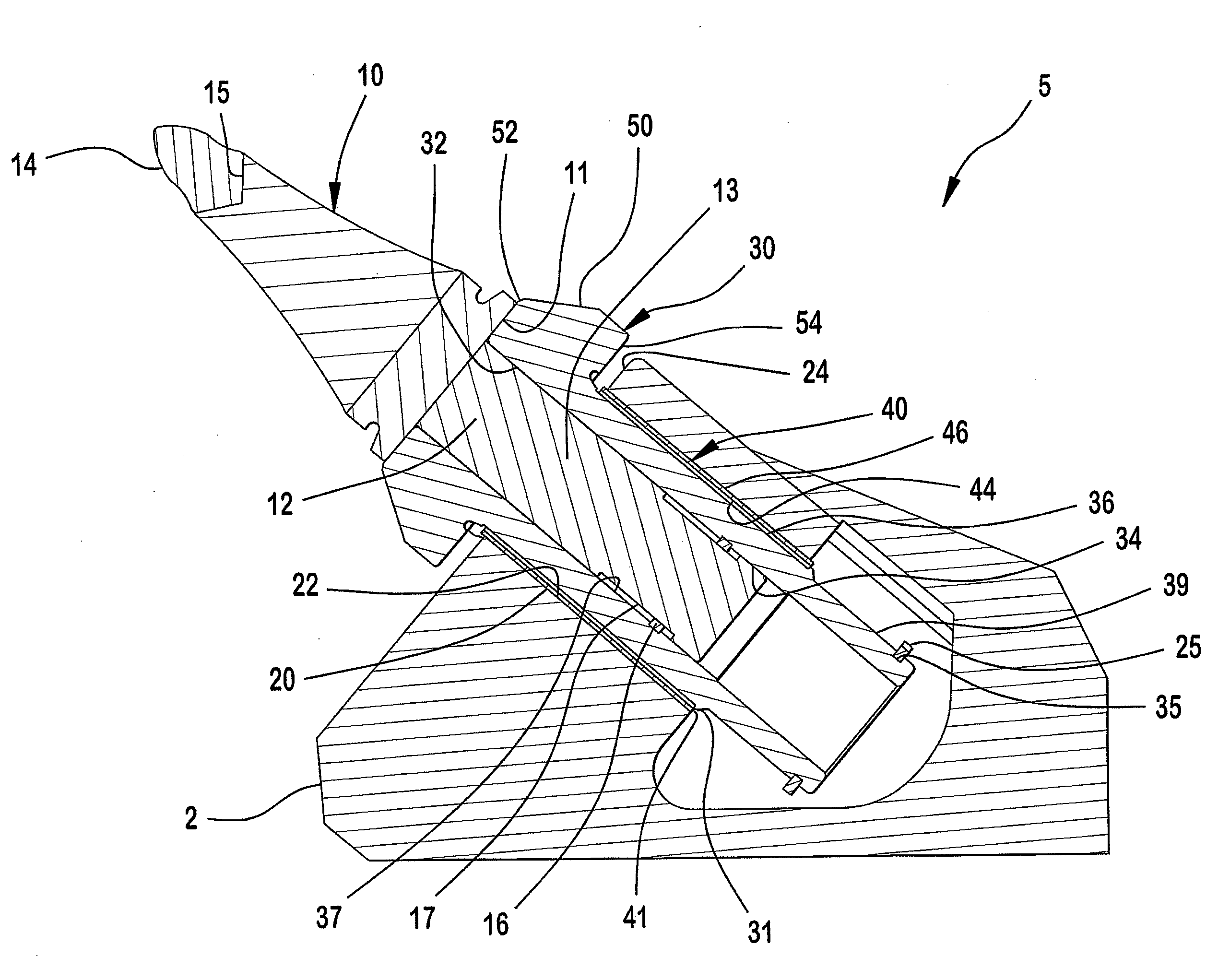
[0042]Referring to FIGS. 1 to 9 there is shown a cutting pick and mounting assembly 5 (See FIG. 9), and components thereof, in accordance with an embodiment of the invention disclosed herein. The cutting pick and mounting assembly 5 is mounted to a cutting pick mounting block 2 to form part of a cutting assembly which can include a rotary cutter, or any other form of cutter, of a piece of mining or excavation equipment (not shown).

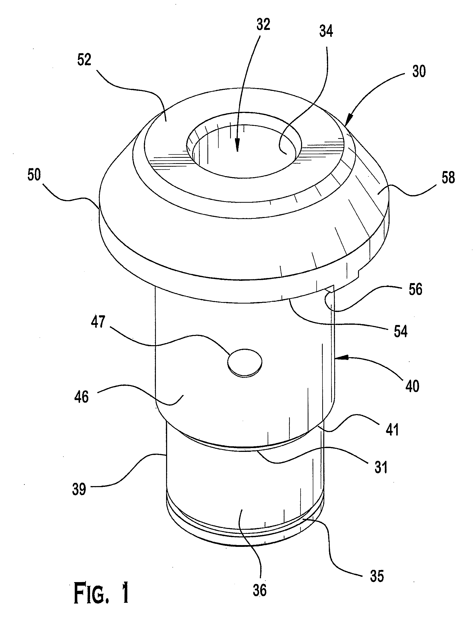
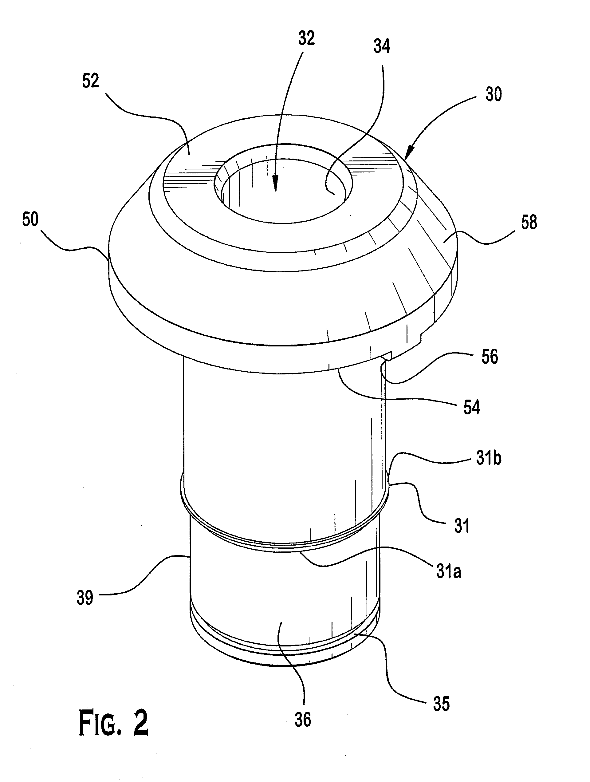
[0043]The cutting pick and mounting assembly 5 includes a cutting pick 10, an inner sleeve 30 and an outer sleeve 40. The cutting pick 10 includes a shank 12 that is receivable within a cutting pick opening 32 within the inner sleeve 30. The inner sleeve 30 is receivable within an inner sleeve opening 42 within the outer sleeve 40 which in turn is receivable within a cutting pick mounting hole 20 extending through a support surface 24 of the cutting pick mounting block 2. Accordingly, the shank 12, the inner sleeve 30 and the outer sleeve 40 are positioned...


PUM


Abstract

To alleviate the problem associated with wear of either the shank of the cutting pick or the surface defining the cutting pick mounting hole, a cutting pick and mounting assembly is provided including a cutting pick having a shank and a cutting tip, a cutting pick mounting hole extending through a support surface within which the shank of the cutting pick is received such that the cutting tip projects from the hole; an inner sleeve having a cutting pick opening within which the shank of the cutting pick extends; an outer sleeve having an inner sleeve opening within which the inner sleeve and the shank of the cutting pick extend; wherein the shank, the inner sleeve and the outer sleeve are positioned concentrically within the cutting pick mounting hole.

Description

CROSS-REFERENCE TO PRIOR APPLICATION[0001]This application claims priority to Australian Application No. 2008230023 filed Oct. 20, 2008, which is incorporated by reference herein.FIELD OF THE INVENTION[0002]The present invention relates to cutting tools used for mining and excavation purposes. The present invention has been developed principally for use in the mining of ore and in that use, typically underground ore mining. It will therefore be convenient to describe the invention in relation to that use although it will be readily appreciated that the invention could be employed for any mining or excavation operation to which its function is suitable.BACKGROUND OF THE INVENTION[0003]Equipment used to mine or excavate in hard earth can include rotary cutters in which a rotating drum that carries a plurality of projecting cutting bits or picks is brought into engagement with an earth face. The picks bite into the earth face as they rotate with the drum to impact against and to dislod...

Claims


Application Information

Patent Timeline
IPC IPC(8): E21C35/197E21C35/183
CPCE21C35/197
Inventor SLEEP, KEITHWEAVER, STEVEN
Owner SANDVIK INTELLECTUAL PROPERTY AB
Why Eureka
Eureka Blog
Learn More