System With Selective Narrow FOV and 360 Degree FOV, And Associated Methods

a narrow field of view and selective technology, applied in the field of selective narrow field of view and 360 degree fov, can solve the problems of serious drawbacks of all existing wide field of view methods, and achieve the effect of increasing magnification

Inactive Publication Date: 2011-07-07
FIVEFOCAL
View PDF17 Cites 143 Cited by
  • Summary
  • Abstract
  • Description
  • Claims
  • Application Information

AI Technical Summary

Problems solved by technology

All of the existing wide field of view methods present serious drawbacks when trying to both image a panoramic scene for overall situational awareness and create a high resolution within the panoramic field of view for tasks requiring greater image detail.

Method used


Image

  • System With Selective Narrow FOV and 360 Degree FOV, And Associated Methods
  • System With Selective Narrow FOV and 360 Degree FOV, And Associated Methods
  • System With Selective Narrow FOV and 360 Degree FOV, And Associated Methods

Examples


Embodiment Construction

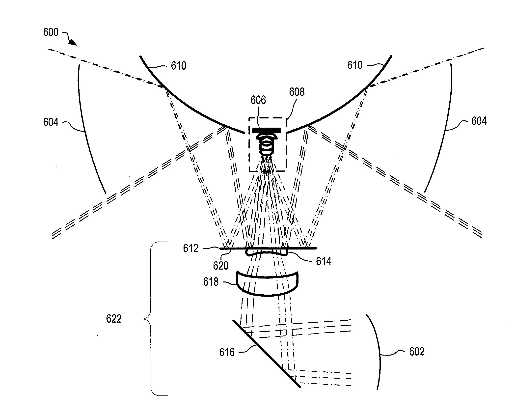
[0048]In the following descriptions, the term “optical channel” refers to the optical path, through one or more optical elements, from an object to an image of the object formed on an optical sensor array.

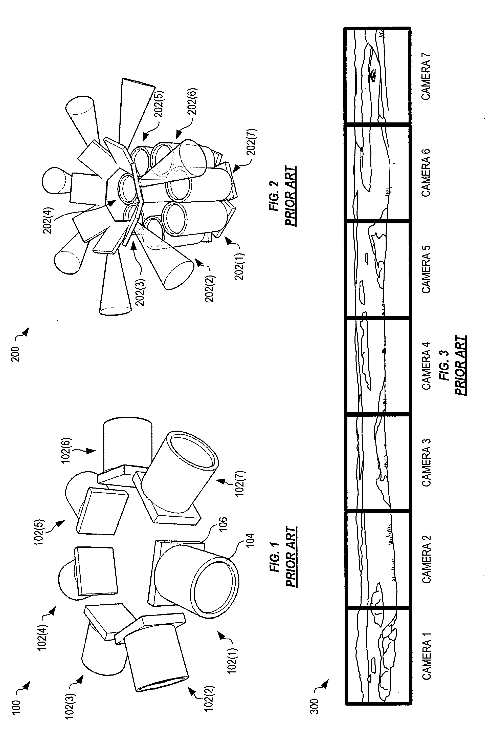
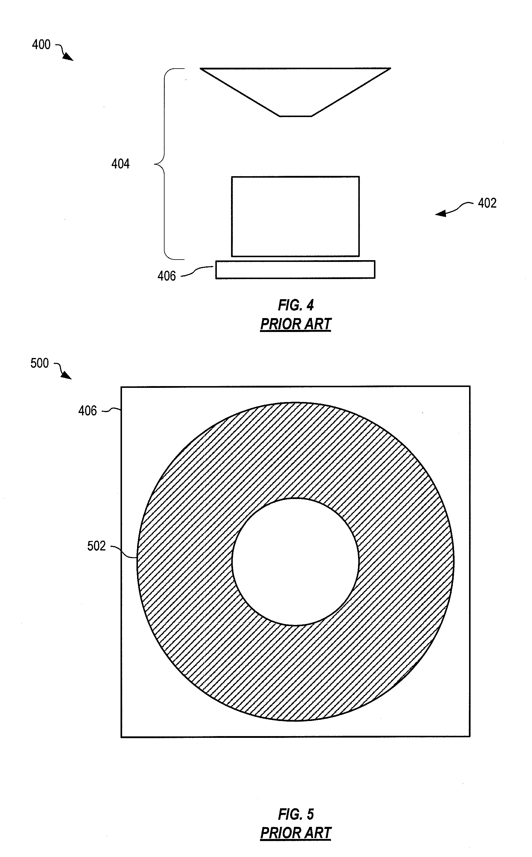
[0049]There are three primary weaknesses that are associated with prior art catadioptric wide field systems: image quality, varying resolution, and inefficient mapping of the image to the sensor array. In prior art catadioptric systems, a custom curved mirror is placed in front of a commercially available objective lens. With this approach, the mirror adds additional aberrations that are not corrected by the lens and that negatively influence final image quality. In the inventive systems and methods described below, this weakness is addressed by an integrated design that uses degrees of freedom within a custom camera objective lens group to correct aberrations that are introduced by the mirror.

[0050]The second prior art weakness is that the resolution of the panoramic channel varie...


PUM


Abstract

Systems and methods image with selective narrow FOV and 360 degree FOV onto a single sensor array. The 360 degree FOV is imaged with null zone onto the sensor array and the narrow FOV is imaged onto the null zone. The narrow FOV is selectively within the 360 degree FOV and has increased magnification as compared to the 360 degree FOV.

Description

RELATED APPLICATIONS[0001]This application claims priority to US Patent Application Ser. No. 61 / 335,159, titled “Compact Foveated Imaging Systems”, filed Dec. 30, 2009, which is incorporated herein by reference.GOVERNMENT RIGHTS[0002]This invention was made with Government support under Phase I SBIR Contract No. N10PC20066 awarded by DARPA, and Phase I SBIR Contract No. W15P7T-10-C-S016 awarded by the ARMY. The Government has certain rights in this invention.BACKGROUND[0003]Many imaging applications need both a panoramic wide field of view image and a narrow, high resolution field of view. For example, manned and unmanned ground, aerial, and water borne vehicles use imagers mounted on the vehicle to assist with situational awareness, navigation obstacle avoidance, 2D and 3D mapping, threat identification and targeting, and other tasks that require visual awareness of the vehicle's immediate and distant surroundings. Certain tasks undertaken by these vehicles also have opposing visua...

Claims


Application Information

Patent Timeline
Patent Type & Authority Applications(United States)
IPC IPC(8): H04N5/225
CPCH04N5/225G02B13/06H04N5/247H04N5/23238H04N23/00H04N23/698H04N23/90
Inventor BATES, ROBERT MATTHEWKUBALA, KENNETH SCOTTBARON, ALAN E.WACH, HANS B.
Owner FIVEFOCAL
Why Eureka
Try Eureka