Method And System For Controlling A Power Converter System Connected To A DC-BUS Capacitor

a power converter and dc-bus capacitor technology, applied in the direction of electric variable regulation, process and machine control, instruments, etc., can solve the problems of increasing the temperature of the components, increasing the amount of electromagnetic interference generated by the power conversion system, and degrading the operation or life of the components of the power conversion system. achieve the effect of reducing the ripple curren

Active Publication Date: 2011-07-07
FORD GLOBAL TECH LLC
View PDF11 Cites 28 Cited by
  • Summary
  • Abstract
  • Description
  • Claims
  • Application Information

AI Technical Summary

Benefits of technology

[0006]Various embodiments of a system or method for controlling a power converter system with first, second, and third phase legs connected to a direct current (DC)-bus capacitor determine direction of current flow in at least two of the phase leg currents and control switching states of the power converter system in response to the current flow directions to reduce ripple current in the DC-bus capacitor.

Problems solved by technology

A high ripple current can increase the temperature of the components connected to a direct current (DC)-bus as well as increase an amount of electromagnetic interference generated by the power conversion system.
Furthermore, a high ripple current can degrade the operation or life of components in the power conversion system as well as decrease the durability or performance of the power conversion system.
A capacitor used to reduce ripple current in a power conversion system can be a relatively expensive component.
However, the expense of the capacitor increases as the size of the capacitor increases.

Method used


Image

  • Method And System For Controlling A Power Converter System Connected To A DC-BUS Capacitor
  • Method And System For Controlling A Power Converter System Connected To A DC-BUS Capacitor
  • Method And System For Controlling A Power Converter System Connected To A DC-BUS Capacitor

Examples


Embodiment Construction

[0017]Embodiments of the present disclosure generally provide a method and system for controlling a power converter system with a direct current (DC)-bus capacitor. In operation, the power converter system is controlled to reduce ripple current flowing through the DC-bus capacitor. As those of ordinary skill in the art will understand, various features of the embodiments illustrated and described with reference to any one of the Figures may be combined with features illustrated in one or more other Figures to produce alternative embodiments that are not explicitly illustrated or described. The combinations of features illustrated provide representative embodiments for typical applications. However, various combinations and modifications of the features consistent with the teachings of the present disclosure may be desired for particular applications or implementations.

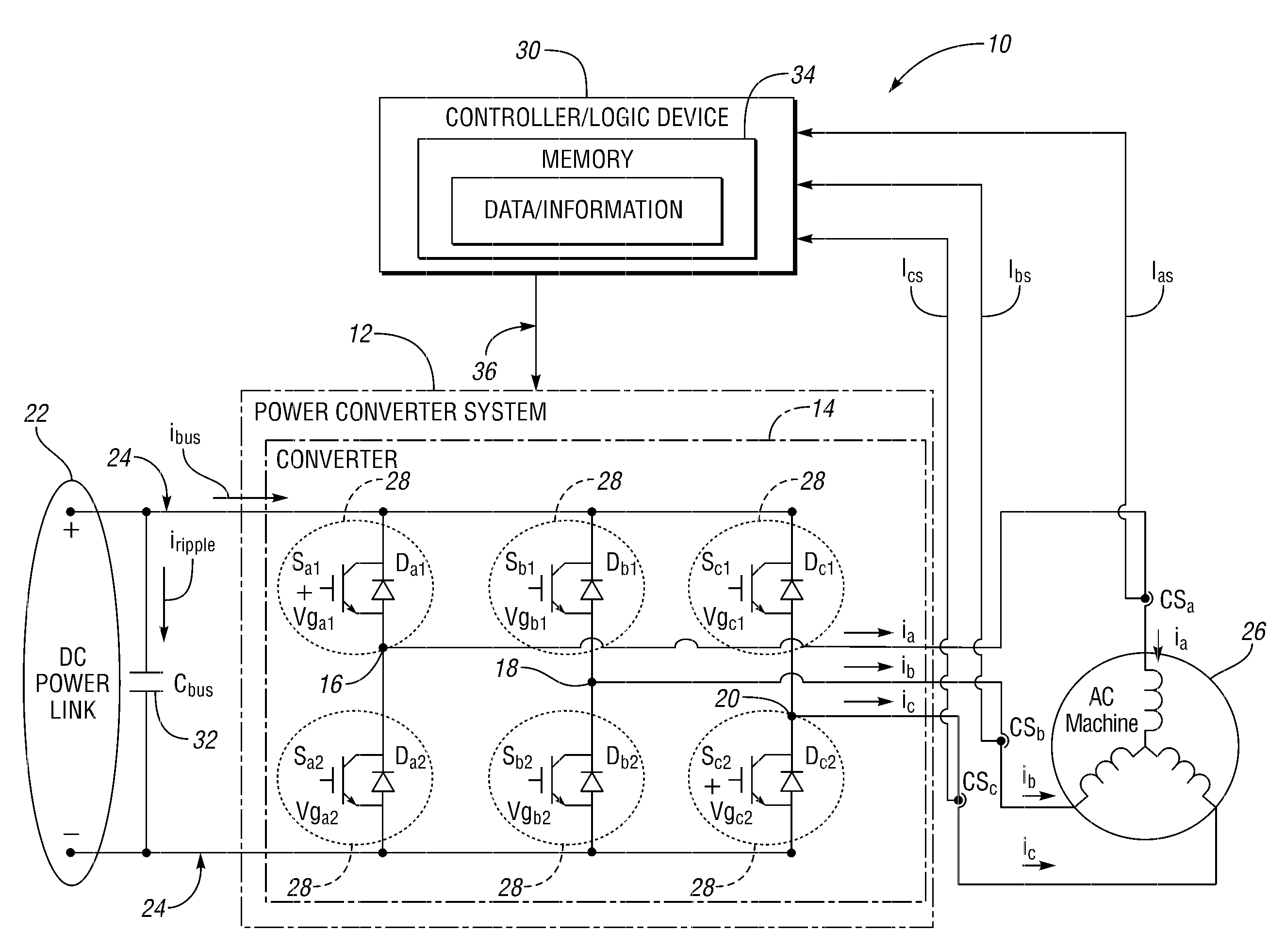
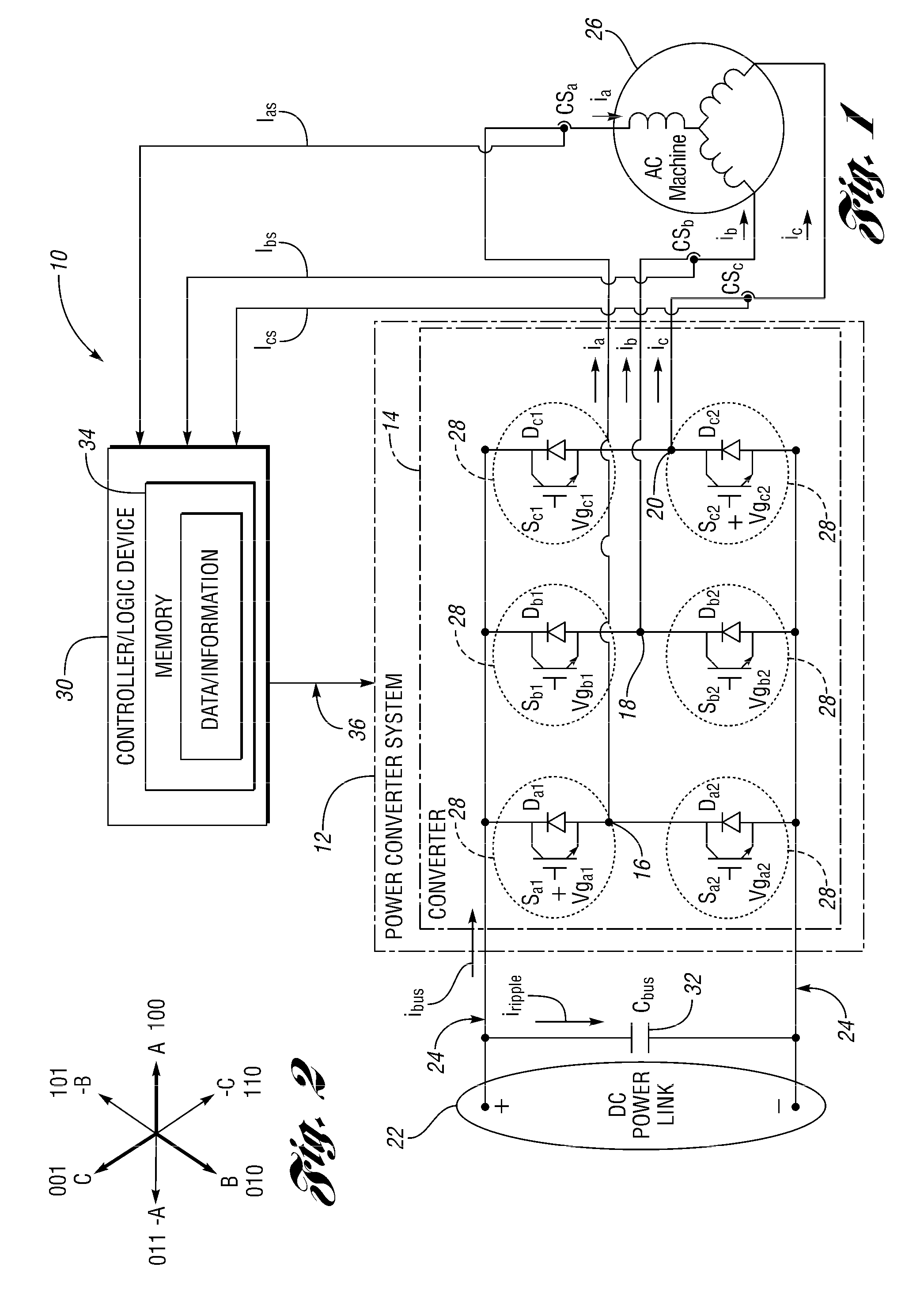
[0018]With reference to FIG. 1, a system 10 is provided for controlling a power converter system 12. The power conve...


PUM


Abstract

A method and system for controlling a power converter system with first, second, and third phase legs with respective first, second, and third associated phase currents determine direction of current flow in at least two phase legs and switch states of the power converter system in response to the current flow directions to reduce ripple current in a connected direct current (DC)-bus capacitor.

Description

BACKGROUND[0001]1. Technical Field[0002]The present invention generally relates to controlling power converter systems.[0003]2. Background Art[0004]The need or desire to reduce ripple current in a power conversion system is well known. A high ripple current can increase the temperature of the components connected to a direct current (DC)-bus as well as increase an amount of electromagnetic interference generated by the power conversion system. Furthermore, a high ripple current can degrade the operation or life of components in the power conversion system as well as decrease the durability or performance of the power conversion system.[0005]A capacitor used to reduce ripple current in a power conversion system can be a relatively expensive component. Larger capacitors are often used as the expected level of ripple current flowing through the DC bus increases. However, the expense of the capacitor increases as the size of the capacitor increases. Thus, it may be desirable to reduce t...

Claims


Application Information

Patent Timeline
Patent Type & Authority Applications(United States)
IPC IPC(8): H02M7/5387
CPCH02M7/53873H02M2007/53876H02M1/15H02M7/53876
Inventor CHEN, CHINGCHIDEGNER, MICHAEL W.THUTA, SATISH
Owner FORD GLOBAL TECH LLC
Why Eureka
Try Eureka