Process and apparatus for removing gaseous contaminants from gas stream comprising gaseous contaminants

a technology of gas stream and gaseous contaminants, which is applied in the direction of separation process, lighting and heating apparatus, coupling device connection, etc., can solve the problems of manual process, difficult to manufacture transformers in combination with chokes, and variable process

Active Publication Date: 2011-07-14
SHELL OIL CO
View PDF16 Cites 21 Cited by
  • Summary
  • Abstract
  • Description
  • Claims
  • Application Information

AI Technical Summary

Problems solved by technology

In practice, it turns out that the manufacture of the transformer in combination with the choke is not easy to do well.
For one thing, the process tends to be manual (and is thus subject to variability) and for another, the intended signal-to-noise levels are low enough that the system is sensitive to external noise and other issues.
Thus, the challenging manufacturing conditions, such as the need to wrap thin wires around a toroidal core in one configuration and then extend the wires in different configurations as they travel away from the toroid, have increased the difficulties in providing a modjack housing with the desired performance.
Furthermore, as system data rates have increased, increasing the data rate of signals that pass through the magnetic jacks has become an increasingly impacted by any inconsistency of the magnetics.
The desire to operate at high date rates thus tends to increase the cost of the magnetic jack.

Method used


Image

  • Process and apparatus for removing gaseous contaminants from gas stream comprising gaseous contaminants
  • Process and apparatus for removing gaseous contaminants from gas stream comprising gaseous contaminants
  • Process and apparatus for removing gaseous contaminants from gas stream comprising gaseous contaminants

Examples


Embodiment Construction

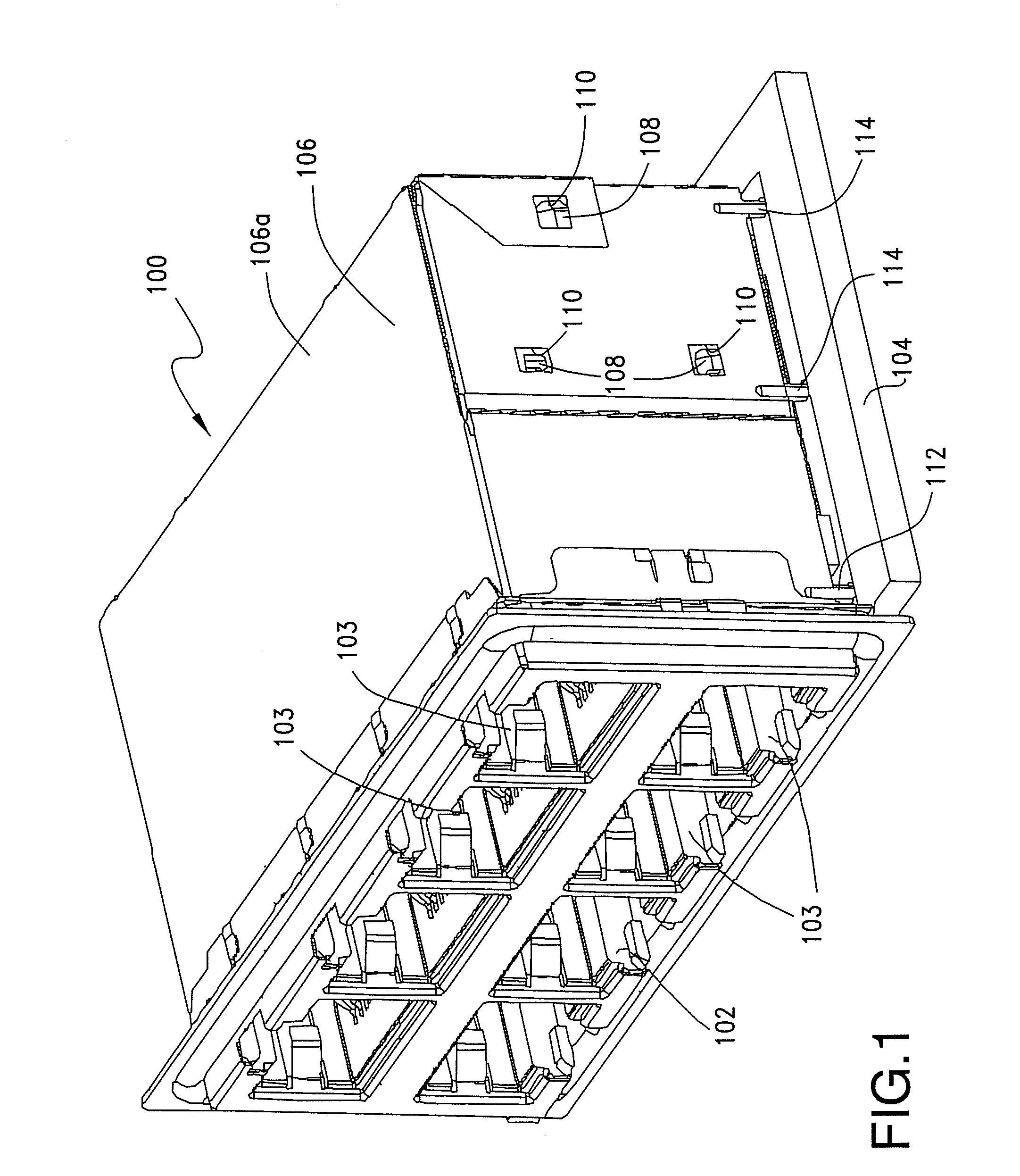
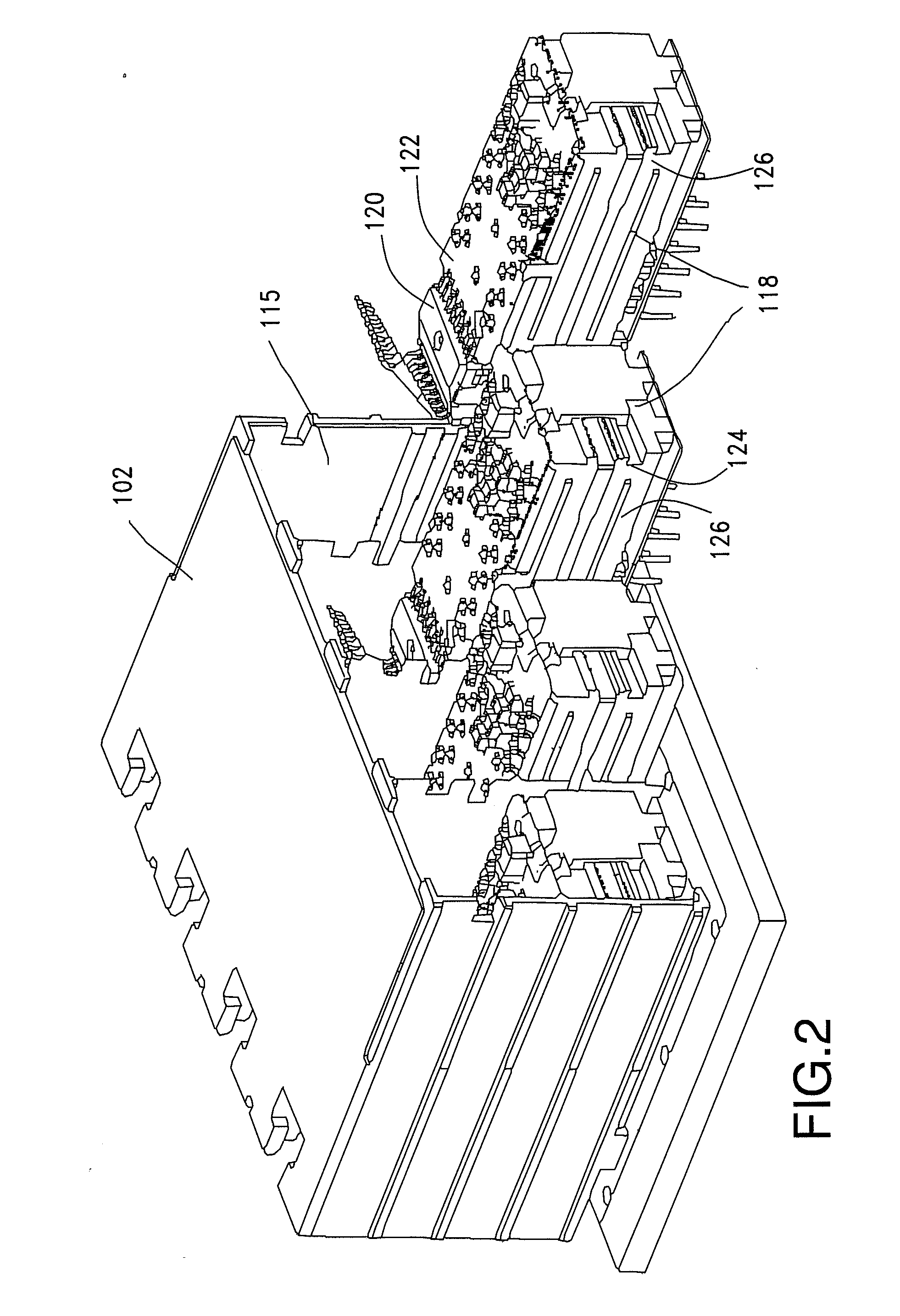
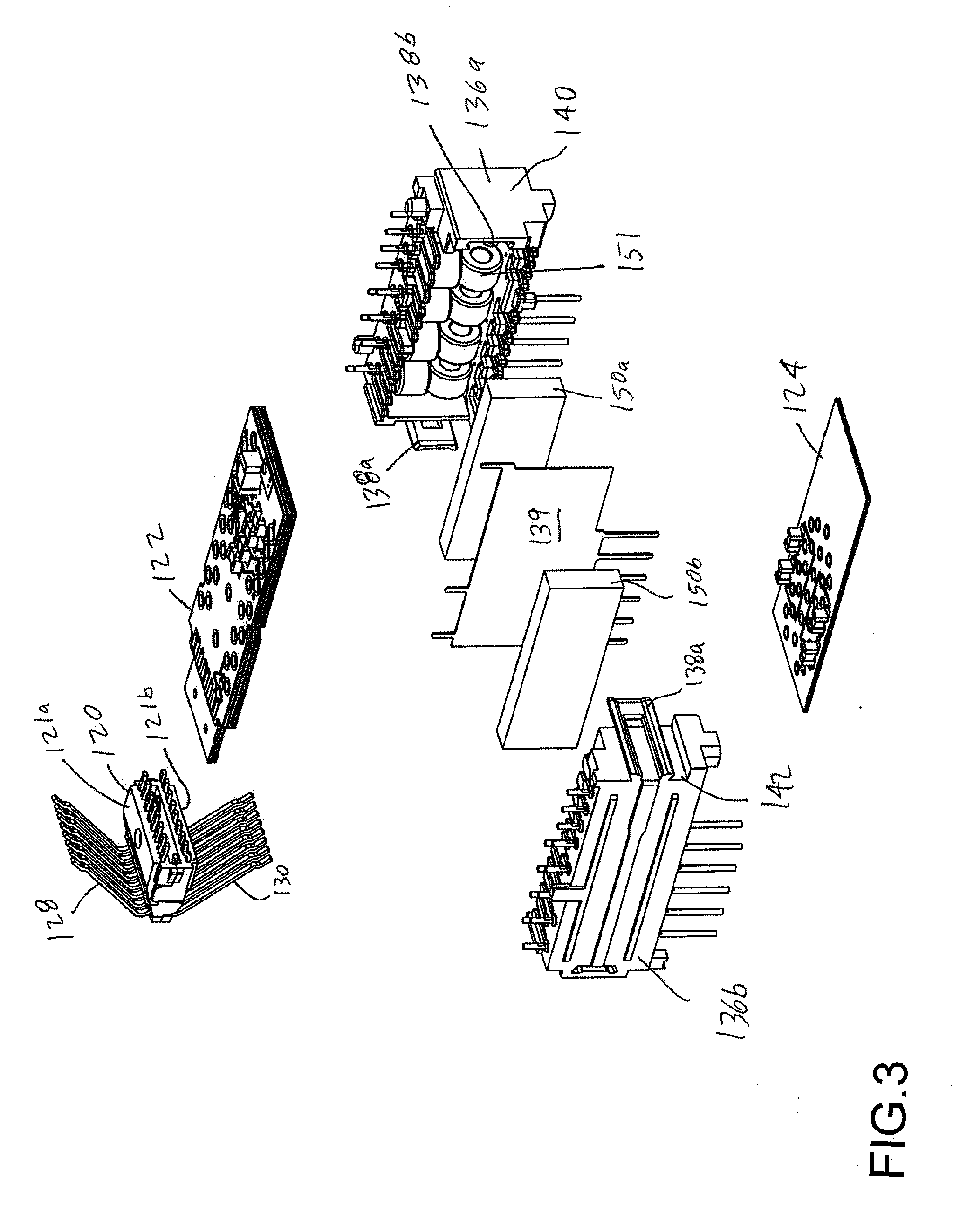
[0037]The following description is intended to convey the operation of exemplary embodiments of the invention to those skilled in the art. It will be appreciated that this description is intended to aid the reader, not to limit the invention. As such, references to a feature or aspect of the invention are intended to describe a feature or aspect of an embodiment of the invention, not to imply that every embodiment of the invention must have the described characteristic. Furthermore, it should be noted that the depicted detailed description illustrates a number of features. While certain features have been combined together to illustrate potential system designs, those features may also be used in other combinations not expressly disclosed. Thus, the depicted combinations are not intended to be limiting unless otherwise noted.

[0038]As noted above, it is generally desirable to minimize electrical inconsistencies in the magnetic properties of a magnetic jack. In addition, tolerances as...


PUM

PropertyMeasurementUnit
dielectric constantaaaaaaaaaa
insertion lossaaaaaaaaaa

Abstract

A transformer has a toroidal core with an opening therein and a plurality of wires to define a central winding section, a plurality of outer twisted wire sections and a plurality of wire proximity sections positioned between each outer twisted wire section and the central winding section. The central winding section includes a plurality of wires wrapped around the toroidal core and coupling a conductor of a primary side of a transformer and a conductor of a secondary side of a transformer. Each outer twisted wire section includes at least a pair of wires twisted together in a predetermined twisted pattern that are electrically connected to but spaced from the central winding section. The wire proximity section is configured to maintain physical proximity between the conductor of the primary side of the transformer and the conductor of the secondary side of the transformer.

Description

[0001]This application claims priority to Provisional Application Ser. No. 61 / 106,510, filed Oct. 17, 2008, which is incorporated herein by reference in its entirety.[0002]The disclosure relates generally to modular telecommunications jacks and, more particularly, to a high data rate capable modular jack.[0003]Modular jack (“modjack”) receptacle connectors mounted to printed circuit boards (“PCBs”) are well known in the telecommunications industry. These connectors are typically used for electrical connection between two electrical communication devices. With the ever-increasing operating frequencies of data and communication systems and the increased levels of encoding used to transmit information, the electrical characteristics of such connectors are of increasing importance. In particular, it is desirable that these modjack connectors do not negatively affect the signals transmitted and where possible, noise is removed from the system. Based on these requirements and desires, var...

Claims


Application Information

Patent Timeline
Patent Type & Authority Applications(United States)
IPC IPC(8): F25J3/08B01D9/04H01R24/58
CPCH01F5/04H01F27/2895H01R24/64H01R13/6658H01R13/6633B01D53/002B01D2256/24C10L3/10C10L3/102F25J3/061F25J2215/04F25J2220/64F25J2240/02F25J2240/40F25J2245/02F25J2270/12F25J2270/60F25J2270/66F25J2290/42F25J3/0635F25J3/067F25J2205/20F25J2220/66F25J2240/60C10L3/104F25J2205/02F25J2210/60F25J2215/60F25J2215/80
Inventor GEERS, HENRICUS ABRAHAMVAN SANTEN, HELMAR
Owner SHELL OIL CO
Why Eureka
Try Eureka