Automatic trim system for fly-by-wire aircraft with unique trim controllers

Active Publication Date: 2011-07-14
SIKORSKY AIRCRAFT CORP
View PDF41 Cites 28 Cited by
  • Summary
  • Abstract
  • Description
  • Claims
  • Application Information

AI Technical Summary

Benefits of technology

A flight control system according to an exemplary aspect of the present disclosure includes a controller which defines a controller displacement and a control surface which defines a control surface authority. A module operable to provide a displacement feel to the controller in response to a remaining portion of the controller displacement being greater than a remaining portion of the control surface authority and the module operable to re-reference a center of the controller displacement to equate the remaining portion of the controller displacement with the remaining portion of the control surface authority in response to the remaining portion of the controller displ

Problems solved by technology

One disadvantage of unique trim controllers may become apparent during aircraft state sensor failure.
During such failures it is no longer possible to provide the full level of augmentation and the flight control system reverts to some combination of rate feedback within a direct rotor control mode.
In the direct rotor control mode, unique trim may complicate flight control since

Method used


Image

  • Automatic trim system for fly-by-wire aircraft with unique trim controllers
  • Automatic trim system for fly-by-wire aircraft with unique trim controllers
  • Automatic trim system for fly-by-wire aircraft with unique trim controllers

Examples


Embodiment Construction

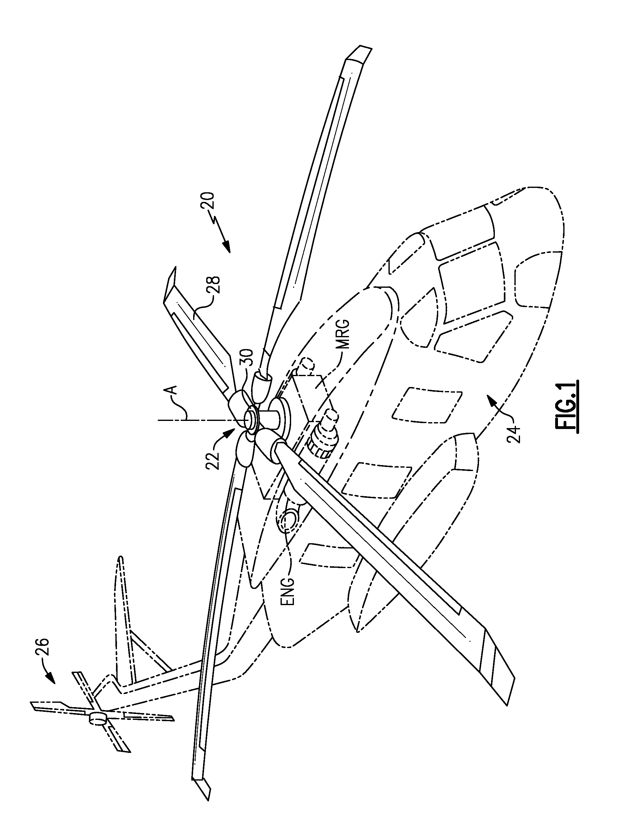
FIG. 1 schematically illustrates an exemplary vertical takeoff and landing (VTOL) rotary-wing aircraft 20. The aircraft 20 in the disclosed, non-limiting embodiment includes a main rotor system 22 supported by an airframe 24 having an extending tail which mounts an anti-torque system 26 such as a tail rotor system. The main rotor system 22 is driven about an axis of rotation A through a main rotor gearbox MRG by one or more engines ENG. The main rotor gearbox MRG may be interposed between the one or more engines ENG, the main rotor system 22 and the anti-torque system 26. The main rotor gearbox MRG is mechanically connected to the main rotor system 22 and to the anti-torque system 26 so that the main rotor system 22 and the anti-torque system 26 may both driven by the main rotor gearbox MRG. The main rotor system 22 includes a multiple of rotor blades 28 mounted to a rotor hub 30. Although a particular helicopter configuration is illustrated and described in the disclosed embodiment...


PUM


Abstract

A flight control system includes a controller which defines a controller displacement and a control surface which defines a control surface authority. A module operable to provide a displacement feel to the controller in response to a remaining portion of the controller displacement being greater than a remaining portion of the control surface authority and the module operable to re-reference a center of the controller displacement to equate the remaining portion of the controller displacement with the remaining portion of the control surface authority in response to the remaining portion of the controller displacement being less than the remaining portion of the control surface authority.

Description

BACKGROUNDThe present disclosure relates to a flight control system, and more particularly to a flight control system auto-trim logic which facilities use of unique trim controllers.A rotary-wing aircraft flight control system typically employs a displacement controller, such as a center cyclic stick, whose position provides an indication to the pilot of the angular disposition or attitude of the rotor. With a displacement controller, there is full correlation between the position of the controller and control surface command. Emergent generations of fly-by-wire (FBW) aircraft such as rotary-wing aircraft provide high levels of augmentation. The pilot-vehicle interface within a rotary-wing aircraft environment often utilize “unique trim” controllers. A unique-trim controller does not produce a fixed amount of output for a given pilot input; instead the unique-trim controller integrates the input over time and produces an output that is a combination of the controller displacement an...

Claims


Application Information

Patent Timeline
IPC IPC(8): B64C13/04
CPCB64C13/503G05D1/0858
Inventor CHEREPINSKY, IGOR
Owner SIKORSKY AIRCRAFT CORP
Why Eureka
Try Eureka