Touch screen calibration and update methods

Active Publication Date: 2011-07-14
NEONODE
View PDF100 Cites 64 Cited by
  • Summary
  • Abstract
  • Description
  • Claims
  • Application Information

AI Technical Summary

Benefits of technology

[0063]There is provided in accordance with an embodiment of the present invention a method of assembling components including inter alia emitters, receivers and lenses, in a device, wherein a component is placed into a cavity on the devi

Problems solved by technology

Such systems are not versatile enough to offer an all-encompassing solution, as they are not easily scalable.
Advantages of resistive touch screens are their low cost, low power consumption and stylus support.
A disadvantage of resistive touch screens is that as a result of the overlay, the screens are not fully transparent.
Another disadvantage is that pressure is required for touch detection; i.e., a pointer that touches the screen without sufficient pressure goes undetected.
As a consequence, resistive touch screens do not detect finger touches well.
Another disadvantage is that resistive touch screens are generally unreadable in direct sunlight.
Another disadvantage is that resistive touch screens are sensitive to scratches.
Yet another disadvantage is that resistive touch screens are unable to discern that two or more pointers are touching the screen simultaneously, referred to as “multi-touch”.
A disadvantage of surface capacitive touch screens is that as a result of the overlay, the screens are not fully transparent.
Another disadvantage is a limited temperature range for operation.
Another disadvantage is a limited capture speed of pointer movements, due to the capacitive nature of the touch screens.
Another disadvantage is that surface capacitive touch screens are susceptible to radio freq

Method used


Image

  • Touch screen calibration and update methods
  • Touch screen calibration and update methods
  • Touch screen calibration and update methods

Examples


Embodiment Construction

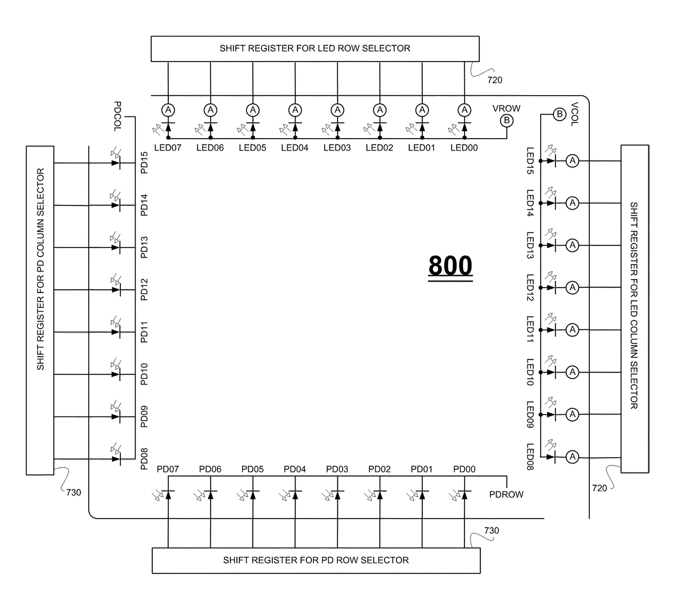
[0152]Aspects of the present invention relate to light-based touch screens and light-based touch surfaces.

[0153]For clarity of exposition, throughout the present specification the term “touch screen” is used as a generic term to refer to touch sensitive surfaces that may or may not include an electronic display. As such, the term “touch screen” as used herein includes inter alia a mouse touchpad as included in many laptop computers, and the cover of a handheld electronic device. The term “optical touch screen” is used as a generic term to refer to light-based touch screens, including inter alia screens that detect a touch based on the difference between an expected light intensity and a detected light intensity, where the detected light intensity may be greater than or less than the expected light intensity. The term “screen glass” is used as a generic term to refer to a transparent screen surface. The screen may be constructed inter alia from glass, or from a non-glass material inc...


PUM


Abstract

A method of calibrating optical components in a light-based touch screen, including providing (i) a display, (ii) a row of light pulse emitters that sequentially transmit light pulses over the display according to calibrated pulse current and pulse duration controls, and (iii) a row of light pulse receivers that receive the light pulses and that output values representing the received light pulses, each receiver having expected values for emitter-receiver pairs when the light pulses are not blocked, determining if each receiver output value for a receiver-emitter pair is within a respective designated range from the corresponding receiver expected value, and when a receiver output value for a receiver-emitter pair is outside the designated range, recalibrating the emitter, including adjusting at least one of the emitter pulse current and pulse duration such that subsequent receiver output values are within the designated range, and updating the receiver expected value for the receiver-emitter pair based on subsequent output values of the receiver.

Description

CROSS REFERENCES TO RELATED APPLICATIONS[0001]This application claims priority benefit of the following five U.S. provisional patent applications, the disclosures of which are hereby incorporated herein by reference.[0002]U.S. Provisional Application No. 61 / 317,255, entitled OPTICAL TOUCH SCREEN WITH WIDE BEAM TRANSMITTERS AND RECEIVERS, filed on Mar. 24, 2010 by inventor Magnus Goertz;[0003]U.S. Provisional Application No. 61 / 317,257, entitled OPTICAL TOUCH SCREEN USING A MIRROR IMAGE FOR DETERMINING THREE-DIMENSIONAL POSITION INFORMATION, filed on Mar. 24, 2010 by inventor Magnus Goertz;[0004]U.S. Provisional Application No. 61 / 379,012, entitled OPTICAL TOUCH SCREEN SYSTEMS USING REFLECTED LIGHT, filed on Sep. 1, 2010 by inventors Magnus Goertz, Thomas Eriksson, Joseph Shain, Anders Jansson, Niklas Kvist and Robert Pettersson;[0005]U.S. Provisional Application No. 61 / 380,600, entitled OPTICAL TOUCH SCREEN SYSTEMS USING REFLECT LIGHT, filed on Sep. 7, 2010 by inventors Magnus Goert...

Claims


Application Information

Patent Timeline
IPC IPC(8): G06F3/042
CPCG06F3/0416G06F3/0418G06F3/042G06F3/0421G06F3/0425G06F2203/04808G06F3/04845G06F3/04883G06F2203/04101G06F2203/04104G06F3/0428G06F3/04166
Inventor GOERTZ, MAGNUSERIKSSON, THOMASSHAIN, JOSEPHJANSSON, ANDERSKVIST, NIKLASPETTERSSON, ROBERTSPARF, LARSKARLSSON, JOHN
Owner NEONODE
Why Eureka
Try Eureka