Optical shuttering device and method of manufacturing the same

a technology of optical shutters and shutters, applied in shutters, instruments, exposure control, etc., can solve the problems of small and thin manufacturing of mechanical optical shutters, and achieve the effect of high response speed and constant physical and mechanical characteristics

Inactive Publication Date: 2011-07-14
SAMSUNG ELECTRONICS CO LTD
View PDF34 Cites 8 Cited by
  • Summary
  • Abstract
  • Description
  • Claims
  • Application Information

AI Technical Summary

Benefits of technology

[0012]As such, in the optical shuttering device, the roll-up blades may be formed as a thin layer made of a single conductive material. Accordingly, unlike a conventional doubled-layered, roll-up blade composed of two layers that are made of heterogeneous materials having a large CTE difference therebetween, the roll-up blades may show constant physical and mechanical characteristics within the operating temperature range of an image pickup device (or the optical shuttering device). In particular, the optical shuttering deice including the roll-up blades may have neither RoC changes nor changes in operating speed due to changes in temperature, while ensuring high response speed.

Problems solved by technology

Further, as electronic devices such an image pickup device are becoming increasingly small and slimline, a mechanical optical shutter needs to be manufactured to be small and thin.

Method used


Image

  • Optical shuttering device and method of manufacturing the same
  • Optical shuttering device and method of manufacturing the same
  • Optical shuttering device and method of manufacturing the same

Examples


Embodiment Construction

[0028]The following description is provided to assist the reader in gaining a comprehensive understanding of the methods, apparatuses, and / or systems described herein. Accordingly, various changes, modifications, and equivalents of the methods, apparatuses, and / or systems described herein will be suggested to those of ordinary skill in the art. Also, descriptions of well-known functions and constructions may be omitted for increased clarity and conciseness.

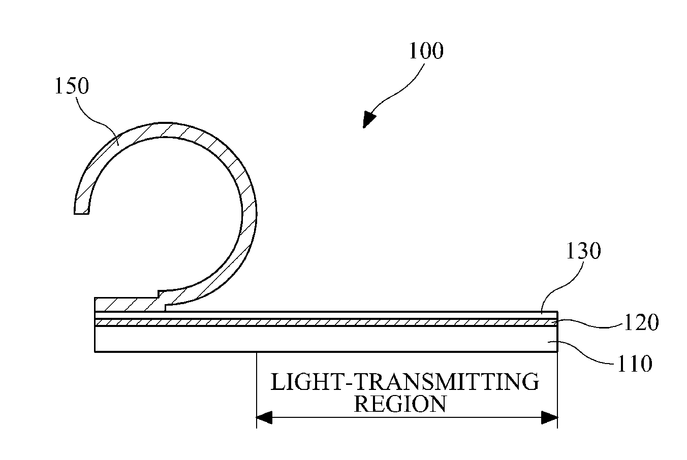
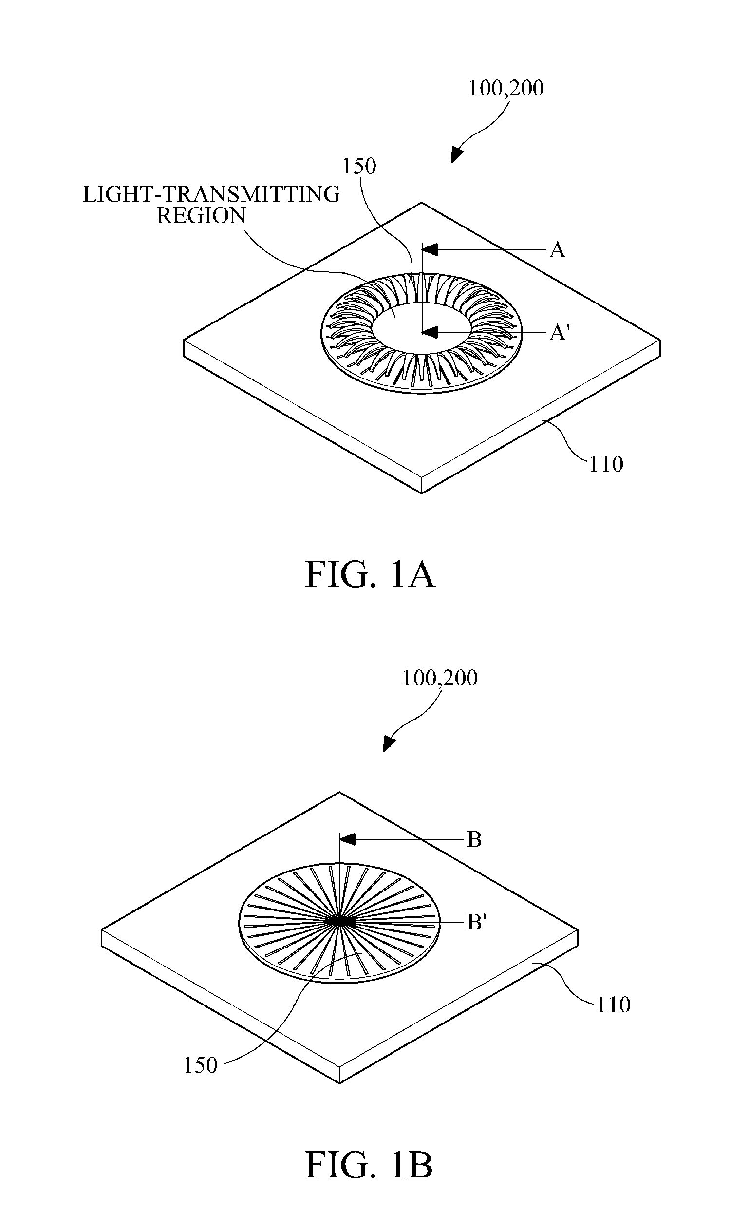
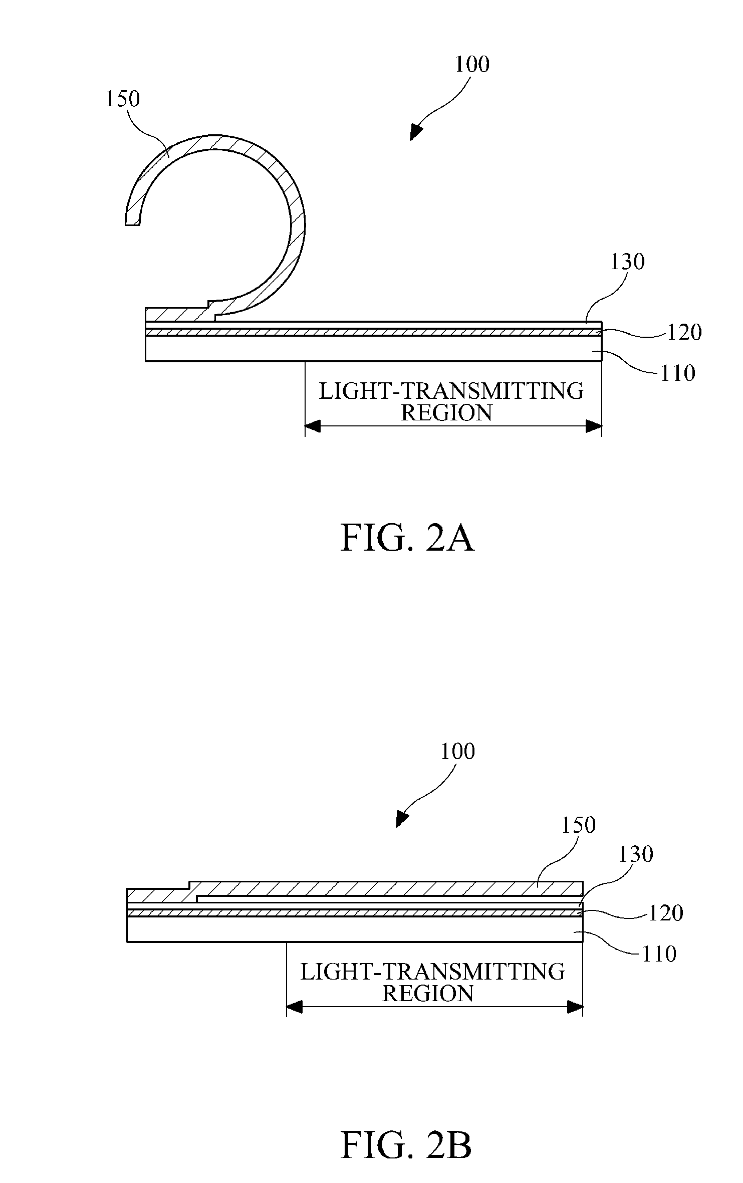
[0029]FIGS. 1A and 1B are perspective views illustrating a configuration of an optical shuttering device 100, wherein FIG. 1A shows a state where the optical shuttering device 100 passes light and FIG. 1B shows a state where the optical shuttering device 100 blocks light. FIG. 2A is a cross-sectional view of the optical shuttering device 100 taken along a line AA′ of FIG. 1A, and FIG. 2B is a cross-sectional view of the optical shuttering device 100 taken along a line BB′ of FIG. 1B. Referring to FIGS. 1A, 1B, 2A and 2B, the optic...


PUM


Abstract

Provided is an optical shuttering device and a method of manufacturing the same. Device includes a roll-up blade that stays in a rolled-up state while no driving voltage is applied thereto and flattens to shutter a light-transmitting region when a predetermined driving voltage is applied to the roll-up blade. The roll-up blade may be provided as a single roll-up blade or as a plurality of roll-up blades such that the roll-up blade(s) shutters a a portion or the entirety of the light-transmitting region. The roll-up blade may be formed as a thin layer made of a single opaque, conductive material. As a single-layered structure, the roll-up blade may spontaneously roll up due to a stress gradient that is made in a thickness direction of the roll-up blade, and as a multi-layered structure, the roll-up blade may spontaneously roll up due to differences in mean stress of the multi layers.

Description

CROSS-REFERENCE TO RELATED APPLICATION[0001]This application claims priority from Korean Patent Application No. 10-2010-0001988, filed on Jan. 8, 2010, the entire disclosure of which is incorporated herein by reference for all purposes.BACKGROUND[0002]1. Field[0003]The following description relates to digital imaging, and more particularly, to a micro mechanical global shutter and iris for digital imaging.[0004]2. Description of the Related Art[0005]Digital convergence is becoming increasingly widespread mostly due to the development of digital technologies. Digital convergence is most prominent in the field of media and communications. A representative digital convergence product is a so-called “camera phone” where an image pickup module such as a digital camera or a digital camcorder is combined with a mobile phone. Such an image pickup device has become commonly installed in various electronic devices including mobile phones, digital cameras, digital camcorders, laptop computers,...

Claims


Application Information

Patent Timeline
Patent Type & Authority Applications(United States)
IPC IPC(8): G02B26/02B05D5/12
CPCG03B9/28G02B26/02G02F1/00G03B7/08G03B9/02H04N23/00
Inventor HONG, SEOG-WOOKIM, CHE-HEUNGLEE, JOO-HO
Owner SAMSUNG ELECTRONICS CO LTD
Why Eureka
Try Eureka