Fixing Device

a fixing device and fixing device technology, applied in the field of fixing devices, can solve the problems of increasing reducing the size of the fixing device, and achieve the effects of reducing the size of the fixing device, and reducing the clearance between the heater and the nip member

Active Publication Date: 2011-07-14
BROTHER KOGYO KK
View PDF14 Cites 53 Cited by
  • Summary
  • Abstract
  • Description
  • Claims
  • Application Information

AI Technical Summary

Benefits of technology

[0009]According to one or more aspects of the disclosure, the nip member may be moved relative to the backup member by moving the first members relative to the second member. Therefore, the nip state may be suitably changed. In addition, the nip member and the heater may be integrally supported by the first supporting members. Therefore, the clearance between the heater and the nip member may be reduced, and the size of the fixing device may be reduced relative to a conventional fixing device.
[0010]The present disclosure may change the nip state between a nip member and a backup member and may reduce the size of a fixing device.

Problems solved by technology

However, in the case of such a structure that moves only the nip plate toward and away from the pressure roller, the clearance between the nip plate and the heater needs to be large to prevent the nip plate from coming into contact with the heater that does not move relative to the pressure roller.
This increases the size of the fixing device.
The present disclosure may change the nip state between a nip member and a backup member and may reduce the size of a fixing device.

Method used


Image

  • Fixing Device
  • Fixing Device
  • Fixing Device

Examples


Embodiment Construction

[0021]Next, embodiments of the present disclosure will be described in detail with reference to the drawings. First, a description will be given of the outline structure of a laser printer 1 (image forming apparatus) including a fixing device 100 according to an embodiment of the present disclosure, and then a description will be given of the detailed structure of the fixing device 100.

[0022]It is noted that various connections are set forth between elements in the following description. It is noted that these connections in general and, unless specified otherwise, may be direct or indirect and that this specification is not intended to be limiting in this respect.

[0023]Outline Structure of Laser Printer

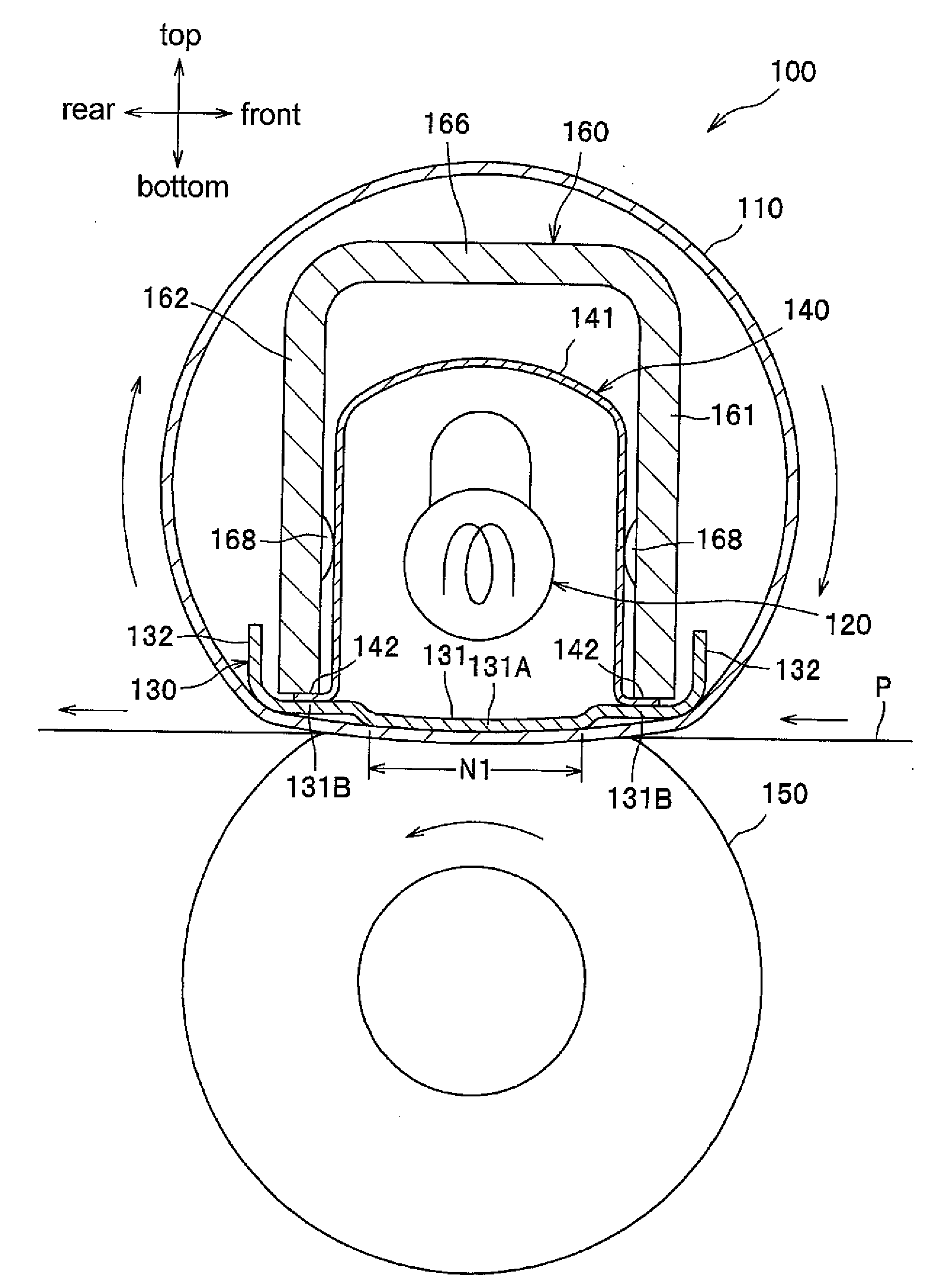
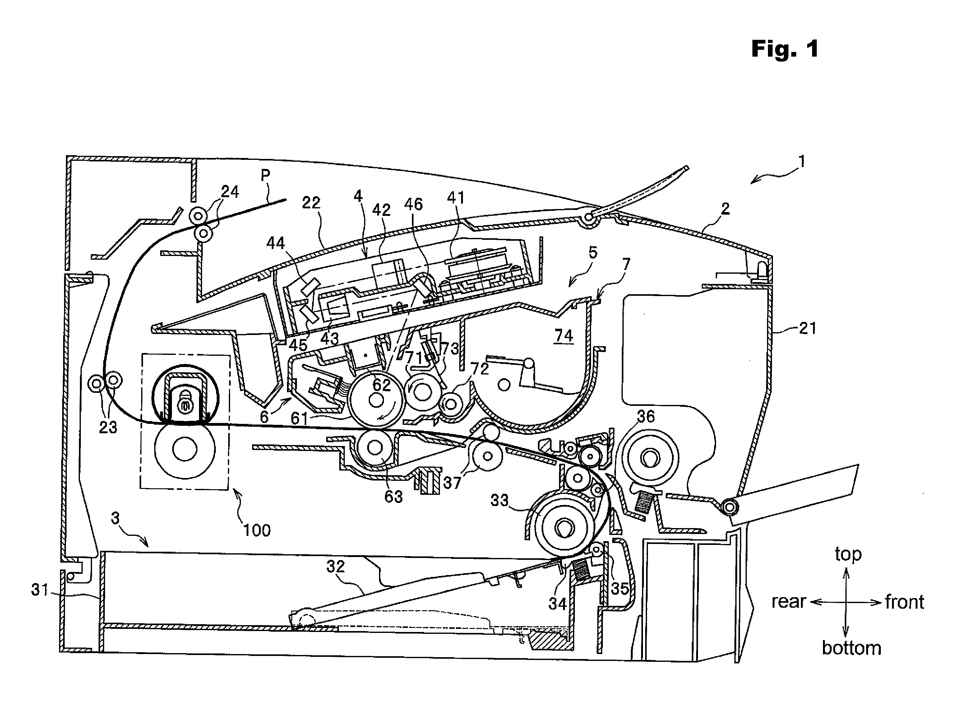
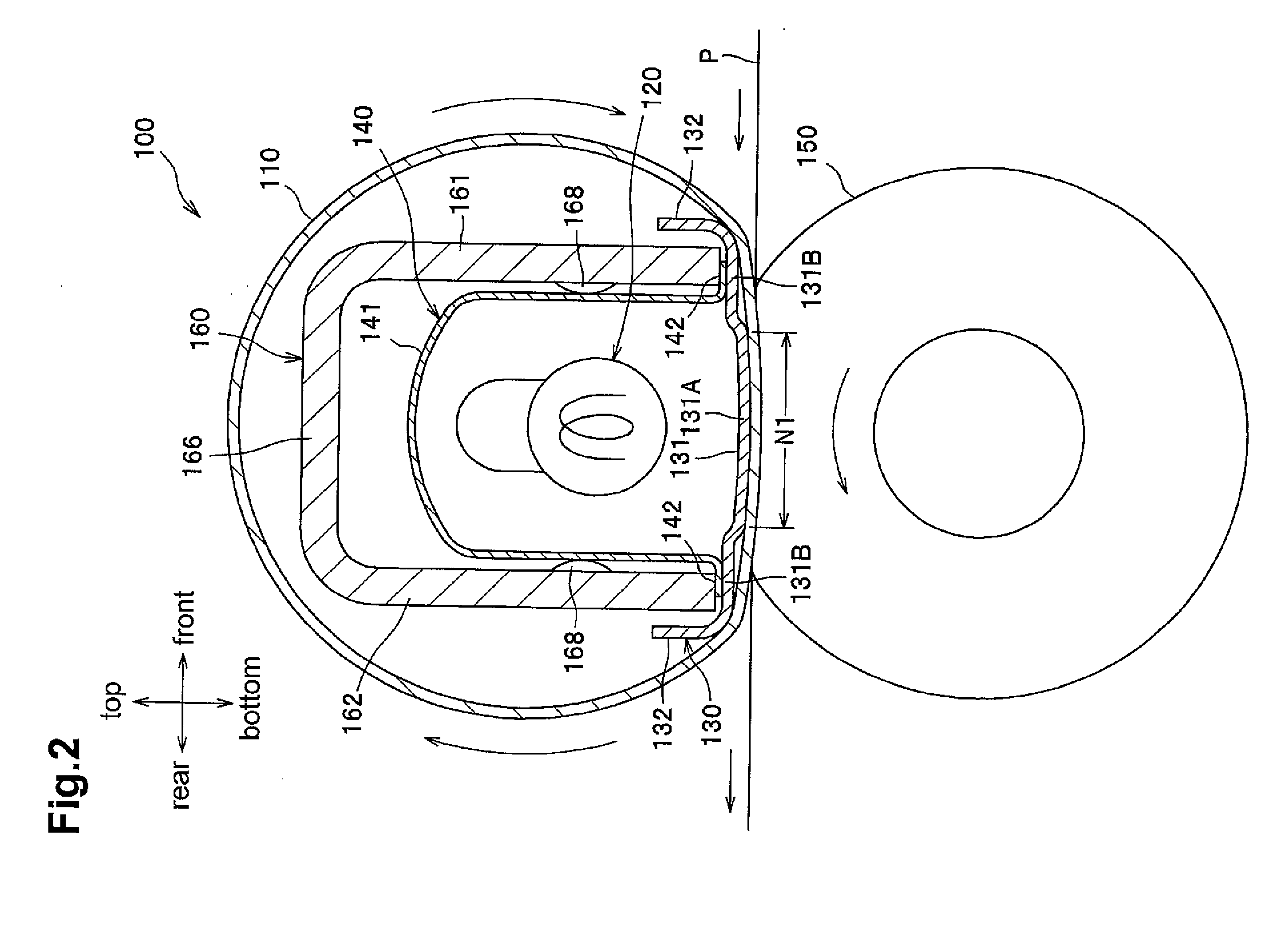
[0024]As shown in FIG. 1, a laser printer 1 includes a body casing 2, a sheet feeder unit 3 that feeds a sheet P of paper as an example of a recording sheet, an exposure device 4, a process cartridge 5 that transfers a toner image (developer image) onto the sheet P, and a fixing devi...


PUM


Abstract

A fixing device includes a tubular fusing film, a heater, a nip member, a backup member, a backup member, first supporting member, and a second supporting member. The heater may be disposed inside the tubular shape of the fusing film. The nip member may be disposed so as to be in sliding contact with the inner surface of the fusing film and heated by the heater. The backup member may form a nip portion between the backup member and the fusing film with the fusing film between the backup member and the nip member. The first supporting member may be configured to integrally support the heater and the nip member. The second supporting member may be configured to movably support the first supporting member so that the nip member moves relative to the backup member.

Description

CROSS REFERENCE TO RELATED APPLICATION[0001]This application claims priority to Japanese Patent Application No. 2009-297130, filed Dec. 28, 2009, the entire subject matter and disclosure of which is incorporated herein by reference.BACKGROUND[0002]1. Technical Field[0003]Aspects of the disclosure relate to a fixing device that thermally fuses a developer image transferred to a recording sheet.[0004]2. Description of the Related Art[0005]A fixing device including a cylindrical fusing film, a heater disposed inside the fusing film, and a heating plate (nip plate) that forms a nip portion between the heating plate and a pressure roller with the fusing film therebetween is known as a fixing device used in an electrophotographic image forming apparatus. In this fixing device, a sheet of paper is conveyed through the nip portion between the fusing film supported by the nip plate and the pressure roller, and a developer image on the sheet is thermally fused in the nip portion.[0006]Such a ...

Claims


Application Information

Patent Timeline
Patent Type & Authority Applications(United States)
IPC IPC(8): G03G15/20
CPCG03G15/2064G03G2215/2035G03G15/206G03G2215/2032G03G15/2053G03G15/2089G03G15/2032
Inventor FUJIWARA, YASUSHISUZUKI, NOBORUISHIDA, KEIMIYAUCHI, YOSHIHIROKONDO, TOMOHIROFUJIWARA, TSUNEOFUJIWARA, ETSUKO
Owner BROTHER KOGYO KK
Why Eureka
Try Eureka