Valve Seat Installation and Retrieval Tool

a tool and valve seat technology, applied in the direction of manufacturing tools, machines/engines, liquid fuel engines, etc., can solve the problems of insufficient utilization of fluids, excess of 10,000 psi, and insufficient use of fluids

Inactive Publication Date: 2011-07-21
WEIR SPM
View PDF15 Cites 56 Cited by
  • Summary
  • Abstract
  • Description
  • Claims
  • Application Information

AI Technical Summary

Benefits of technology

[0011]Preferably, the shaft nut is secured to the shaft by a threaded engagement. This allows the operator to abu

Problems solved by technology

The pressures may exceed 10,000 psi, and the fluids are abrasive.
Because of the severe operating conditions, the operators must change various components such as valves, valve seats and plunger seals frequently.
This can be difficult, pa

Method used


Image

  • Valve Seat Installation and Retrieval Tool
  • Valve Seat Installation and Retrieval Tool
  • Valve Seat Installation and Retrieval Tool

Examples


Embodiment Construction

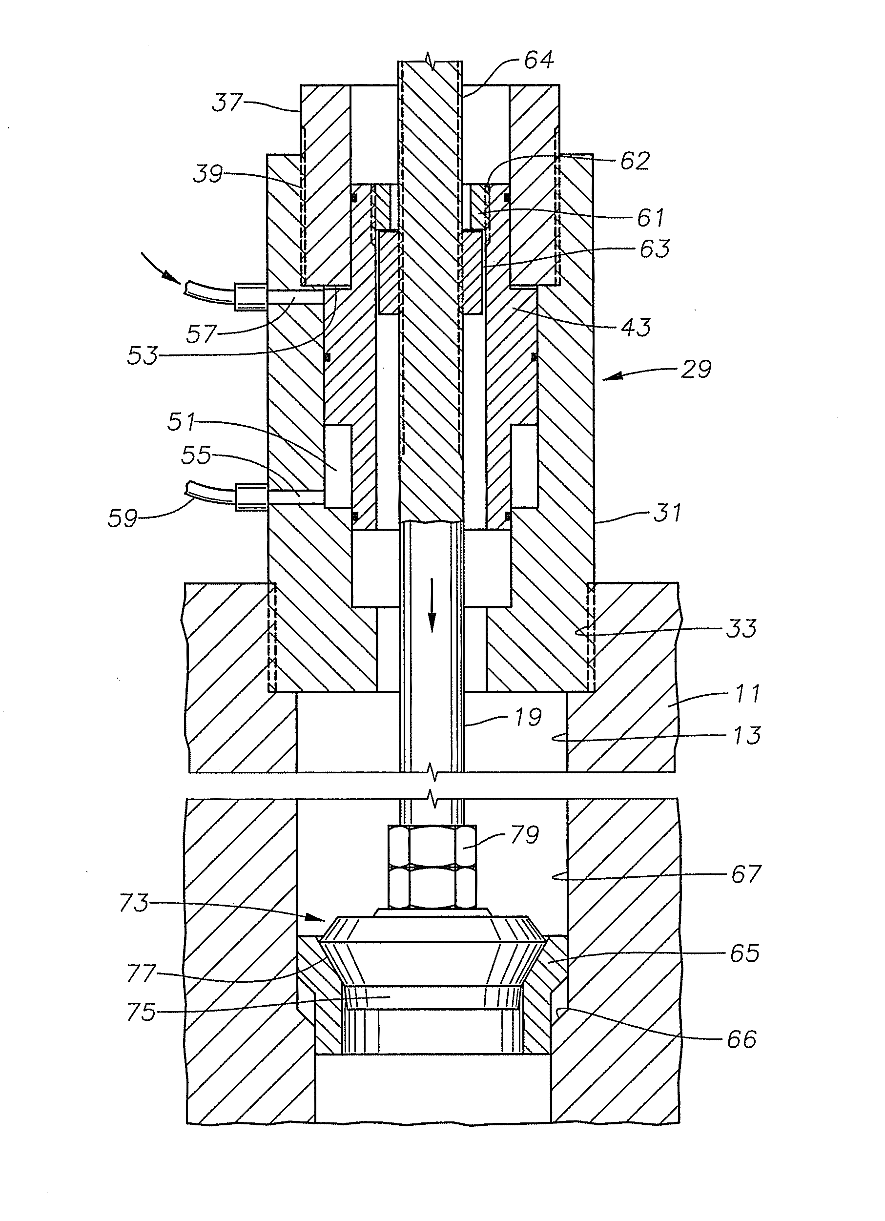
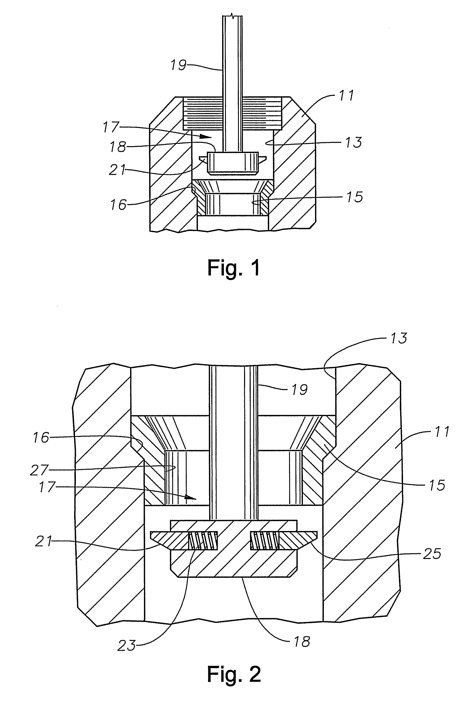
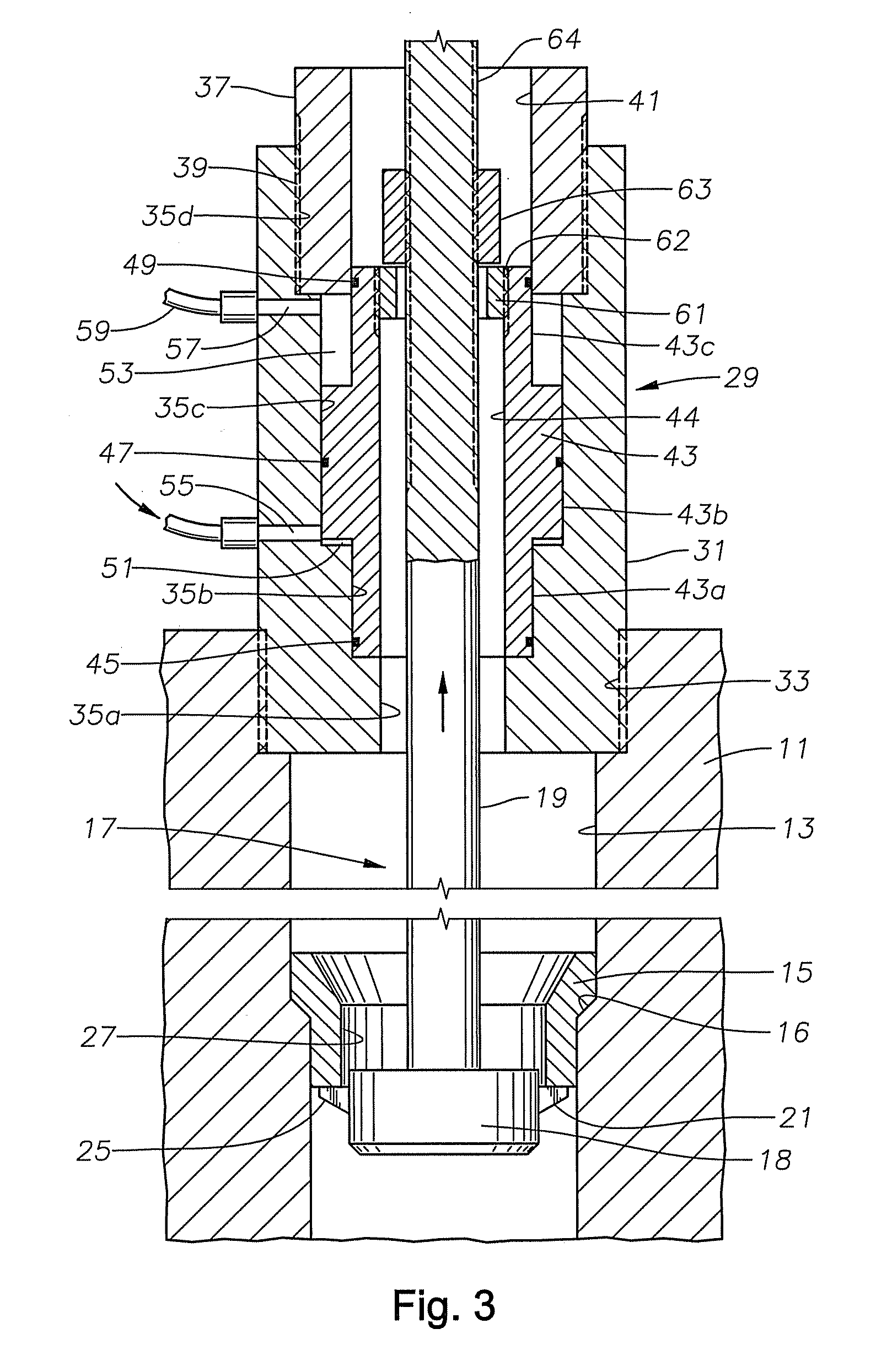
[0020]Referring to FIG. 1, a pump fluid block 11 is shown partially in section. Pump fluid block 11 is a fluid portion of a large reciprocating pump such as used for high pressure fluid injection into oil and gas wells during hydraulic fracturing operations. Pump fluid block 11 has a number of valve passages 13 (only one shown), each containing a valve seat 15. Valve passage 13 is shown extending vertically, but it could be oriented horizontally or in other directions. The terms such as “upper” or “upward” and “lower” or “downward” are used only for convenience. Valve seat 15 is pressed with an interference fit onto an upward facing conical shoulder 16 in valve passage 13. A valve member (not shown) would normally be mounted above valve seat 15, the valve member having a mating surface for engaging valve seat 15 and a spring that urges the valve member against the seat. The valve member will be removed prior to removing valve seat 15.

[0021]FIG. 1 shows a retrieval or removal tool 17...


PUM

PropertyMeasurementUnit
Forceaaaaaaaaaa
Diameteraaaaaaaaaa

Abstract

A tool for replacing a valve seat of a reciprocating pump has a puller shaft connected to a puller head having at least two spring-biased dogs. An operator inserts the puller head into a valve bore and through a valve seat, the dogs retracting as the puller head moves through the valve seat, then snapping back outward. A hydraulic cylinder engages the puller shaft to exert a force on the puller shaft causing the dogs to dislodge the seat. The operator then places a replacement valve seat on a shoulder in the valve bore. The operator attaches an installing head to an installing shaft and inserts the installing head into the valve bore into contact with the replacement valve seat. The hydraulic cylinder applies a force in an opposite direction on the installing shaft to push the replacement valve seat into installed engagement.

Description

CROSS-REFERENCE TO RELATED APPLICATION[0001]This application claims priority to provisional application 61 / 261,632, filed Nov. 16, 2009.FIELD OF THE INVENTION[0002]This invention relates in general to tools for retrieving and installing valve seats in a fluid end of a reciprocating pump.BACKGROUND OF THE INVENTION[0003]One type of well service pump is particularly used for hydraulic fracturing operations, also called “frac” operations. Fluid at high pressure is pumped down the well to cause the producing formation to fracture. Beads may be mixed into fluid being pumped to prop the cracks open. The pressures may exceed 10,000 psi, and the fluids are abrasive.[0004]These pumps are commonly mounted to trucks that are dispensed almost daily for performing frac operations. Because of the severe operating conditions, the operators must change various components such as valves, valve seats and plunger seals frequently. It is important to be able to change out these components quickly.[0005...

Claims


Application Information

Patent Timeline
IPC IPC(8): B23P6/00B23P19/04
CPCF04B53/1087Y10T29/53596Y10T29/49407
Inventor PATEL, PANKAJ H.
Owner WEIR SPM
Why Eureka
Try Eureka