Door breaching projectile system

a projectile and door technology, applied in the direction of hand grenades, ammunition fuzes, weapons, etc., can solve the problems of size and mass of the projectile, inability to achieve optimal use, and inability to meet the needs of the structure,

Inactive Publication Date: 2011-07-21
CHEMRING ORDNANCE
View PDF7 Cites 13 Cited by
  • Summary
  • Abstract
  • Description
  • Claims
  • Application Information

AI Technical Summary

Benefits of technology

[0019]The present invention is a modified 40 mm grenade round designed to breach doors without throwing a substantial amount of shrapnel into a building's interior. The modified round includes a standoff device located on its forward end. The standoff device detonates the explosive charge within the projectile before the nose of the proj

Problems solved by technology

The main difference, however, is the size and mass of the projectile.
However, it is often not optimal in this role.
However—hostile or not—the occupants will not voluntarily open the

Method used


Image

  • Door breaching projectile system
  • Door breaching projectile system
  • Door breaching projectile system

Examples


Embodiment Construction

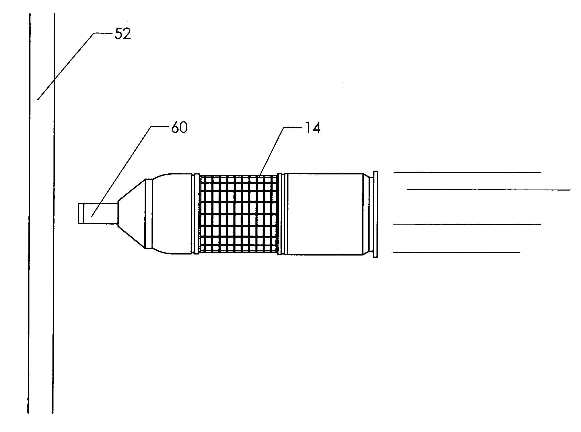
[0074]FIG. 9 shows an elevation view of a projectile 14 made according to the present invention (shown in flight toward a target). The projectile has a central axis of symmetry, about which it spins during flight. The reader will observe that standoff device 60 has been added to the projectile's forward portion along this central axis. The standoff device contacts door 52 and transmits a sharp deceleration to the projectile, causing it to explode. When compared to the prior art projectile's detonation upon contact between the ogive and the door, the detonation in the present case can be said to be “early.” The early detonation is advantageous in certain circumstances—as will be seen.

[0075]FIG. 10 shows the detonation of the projectile by operation of standoff device 60. Explosion 58 has occurred while the majority of the projectile remains outside the door. The resulting blast pressure wave propels the door inward. Flying debris 56 remains primarily outside the door. Thus, the proje...


PUM


Abstract

A modified 40 mm grenade round designed to breach doors without throwing a substantial amount of shrapnel into a building's interior. The modified round includes a standoff device located on its forward end. The standoff device detonates the explosive charge within the projectile before the nose of the projectile actually strikes the target. This early detonation throws a pressure wave again the door's exterior, forcing the door inward. Shrapnel produced by the detonation remains primarily outside the door. Thus, the modified projectile is able to blow open a door without throwing a significant amount of shrapnel into a building's interior.

Description

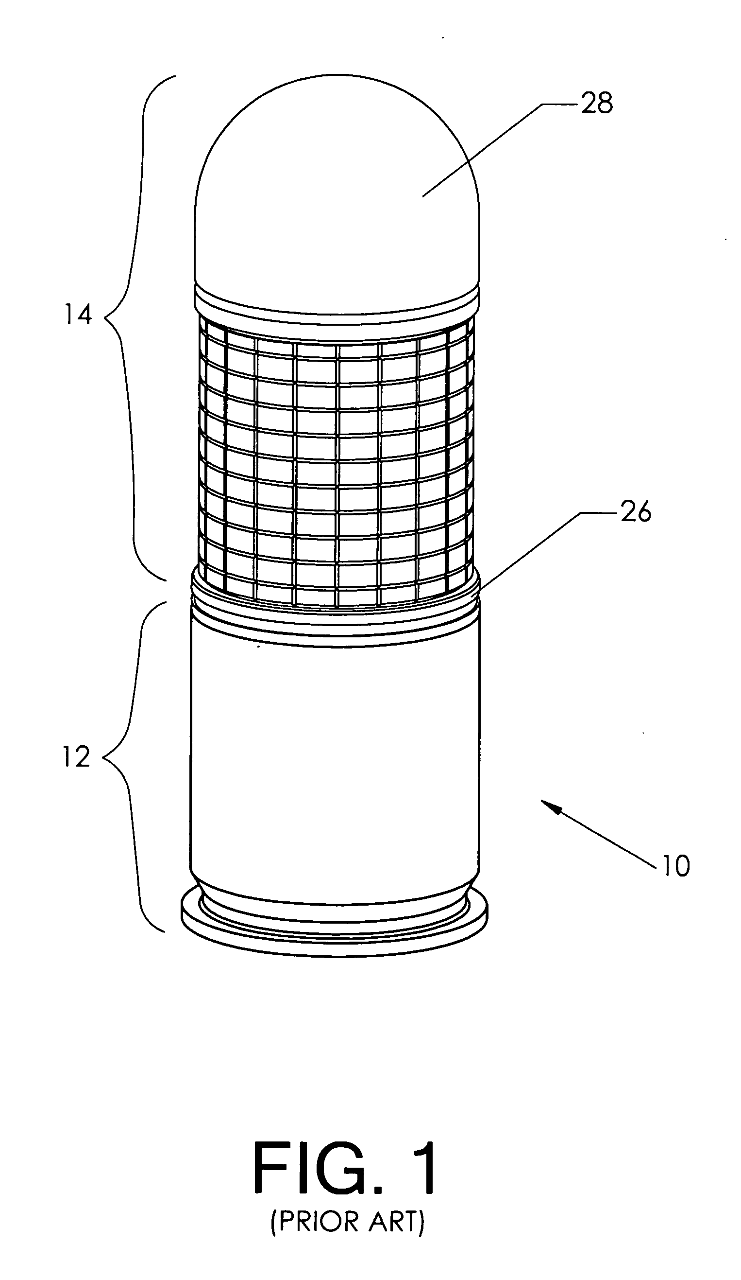
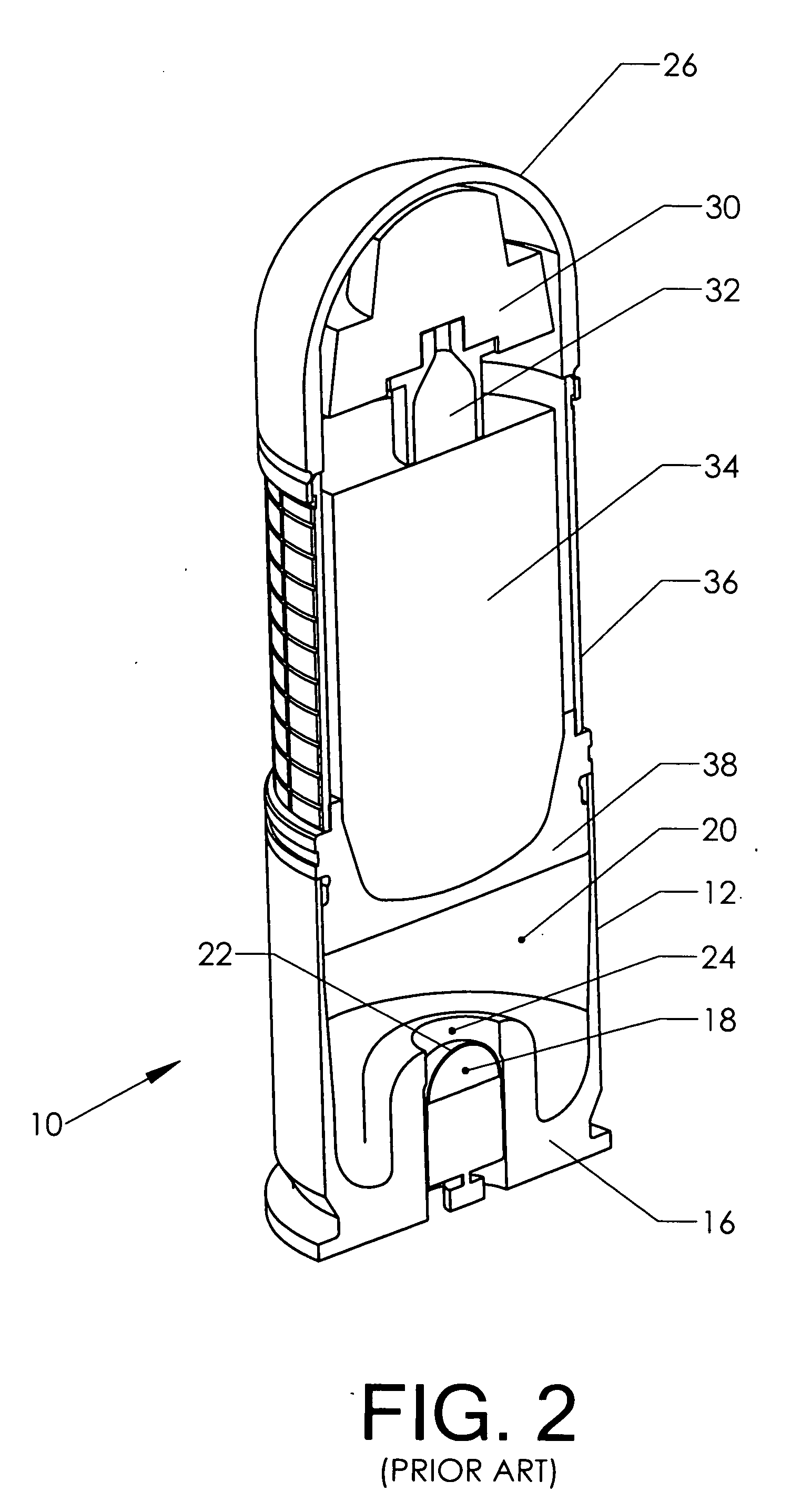
BACKGROUND OF THE INVENTION[0001]1. Field of the Invention[0002]This invention relates to the field of projectile delivery systems. More specifically, the invention comprises a standoff device configured to detonate the explosives in a projectile before the nose of the projectile strikes a target.[0003]2. Description of the Related Art[0004]Although the present invention can be applied to many different types of projectiles, it was primarily developed as a component of existing 40 mm grenade weapons (such as the U.S. Army's M-433). FIG. 1 depicts prior art 40 mm grenade round 10. Its two main components are case 12 (which houses the propulsion system) and projectile 14. The grenade round is designed to be fired from a variety of weapons. One example is the U.S. Army's M-203 grenade launcher which is typically slung beneath the barrel of a rifle such as the M-16A2.[0005]The launching of a 40 mm grenade involves the same principles as a conventional rifle cartridge. The main differenc...

Claims


Application Information

Patent Timeline
IPC IPC(8): F42B30/04F42B5/02
CPCF42B30/04F42B12/204
Inventor VAN STRATUM, BRUCE G.
Owner CHEMRING ORDNANCE
Why Eureka
Try Eureka