Primary Heat Exchanger Design for Condensing Gas Furnace

a heat exchanger and gas furnace technology, applied in the field of gas furnaces, can solve the problems of high manufacturing and other related costs

Active Publication Date: 2011-07-21
CARRIER CORP
View PDF63 Cites 65 Cited by
  • Summary
  • Abstract
  • Description
  • Claims
  • Application Information

AI Technical Summary

Problems solved by technology

However, several requirements and constraints must be taken into account when designing such a primary heat exchanger for achieving optimum performances.
However, such materials are typically expensive and can lead to higher manufacturing and other related costs.

Method used


Image

  • Primary Heat Exchanger Design for Condensing Gas Furnace
  • Primary Heat Exchanger Design for Condensing Gas Furnace
  • Primary Heat Exchanger Design for Condensing Gas Furnace

Examples


Embodiment Construction

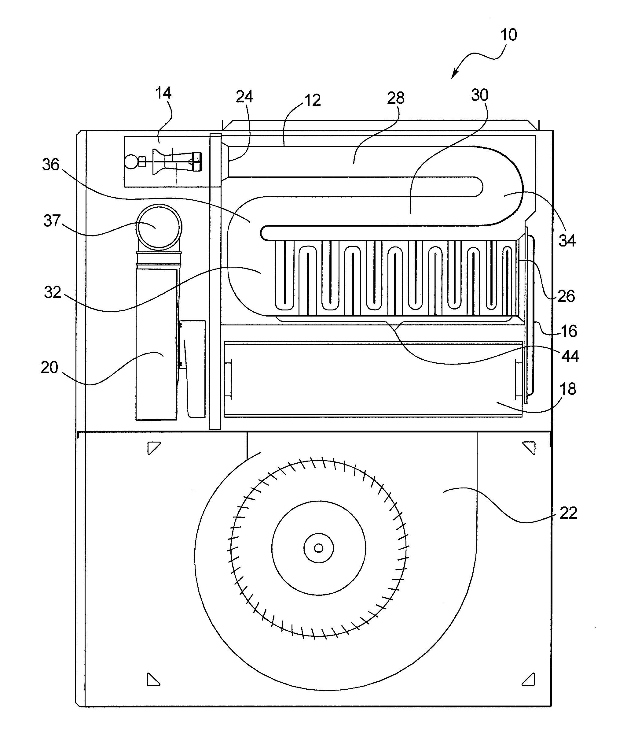
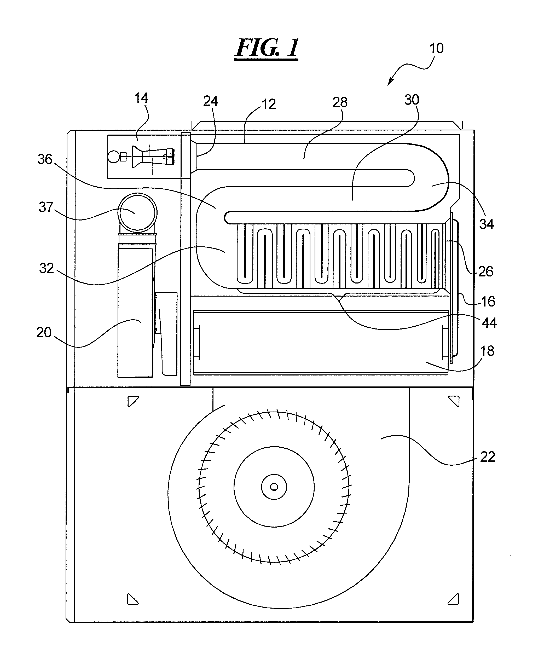
[0022]Referring to FIG. 1, a compact condensing gas furnace 10 employing an exemplary primary heat exchanger 12 (also referred herein as a compact furnace heat exchanger) is shown, in accordance with at least some embodiments of the present disclosure. The gas furnace 10 can further include a burner 14 for combusting air and fuel to produce heated flue gases, a coupling box 16 for transferring the heated flue gases from the burner via the primary heat exchanger 12 to a secondary heat exchanger 18, an inducer 20 for drawing out or venting any exhausted flue gases, and a blower 22 for circulating circulate air in the surrounding areas.

[0023]Although only the primary heat exchanger 12, the burner 14, the coupling box 16, the secondary heat exchanger 18, and the inducer 20 have been shown in FIG. 1 in the gas furnace 10, it will be understood that several other commonly employed components, such as, humidifiers and filters, can additionally be used in conjunction or combination with the...


PUM


Abstract

A compact furnace heat exchanger for a gas furnace is disclosed. The compact furnace heat exchanger may include a first pass having an inlet end, a second pass in fluid communication with the first pass through a first return bend, and a third pass having an outlet end and in fluid communication with the second pass through a second return bend. The third pass may further include a plurality of irregularities for optimizing performance of the compact furnace heat exchanger and the associated gas furnace.

Description

CROSS-REFERENCE TO RELATED APPLICATIONS[0001]This is a non-provisional U.S. patent application, which claims priority under 35 U.S.C. §119(e) to U.S. Provisional Patent Application Ser. No. 61 / 296,505 filed on Jan. 20, 2010, the entirety of which is incorporated by reference herein.FIELD OF THE DISCLOSURE[0002]This disclosure relates to gas furnaces and, more particularly, to primary heat exchangers for condensing gas furnaces.BACKGROUND OF THE DISCLOSURE[0003]A typical gas furnace includes a flame or burner for heating flue gases, a primary heat exchanger for transferring heat from the heated gases to the circulate air, and a blower for circulating the circulate air through a home (or any surrounding area). The gas furnace often also includes an inducer for drawing out or otherwise venting the heated flue gases from the primary heat exchanger.[0004]With respect to the primary heat exchanger in particular, it serves to transfer heat from the heated flue gases to the circulate air, w...

Claims


Application Information

Patent Timeline
Patent Type & Authority Applications(United States)
IPC IPC(8): F24C3/00F28F1/00
CPCF23J15/06F24H3/105F24H8/00Y02E20/346Y02B30/102Y02E20/363F28D1/035Y02B30/00Y02E20/30Y02E20/34
Inventor HAYDOCK, PAUL M.GUPTA, NITU
Owner CARRIER CORP
Why Eureka
Try Eureka