Produce washer and method for continuous motion washing machine

a technology of producing washer and washing machine, which is applied in the direction of washing/rinsing machines for tableware, cleaning using liquids, house cleaners, etc., can solve the problems of performance of the machine, affecting the overall efficiency of the machine, and the difficulty of unloading small items such as produce from the wash tank of the continuous motion washing machine, etc., to achieve the effect of increasing the flow velocity, reducing the disruption of recirculating motion, and reducing the disruption of the r

Active Publication Date: 2011-07-21
UNIFIED BRANDS
View PDF7 Cites 10 Cited by
  • Summary
  • Abstract
  • Description
  • Claims
  • Application Information

AI Technical Summary

Benefits of technology

[0009]The produce basket includes a generally open front face and a top connected to the front face of the basket. Two cross members that function as handles for the basket, as well as providing a rigid framework for the basket, extend across the front face / top portions of the basket. The basket includes a pair of side walls extending from the front face toward a rear wall, a bottom wall, and, in a preferred embodiment, an intermediate angled wall connecting the bottom and rear walls. The intermediate angled wall is angled to prevent interference with the jet stream created by the discharge jet(s) located along the rear wall (or other wall) of the wash tank. A pair of support / pivot pins protrudes from each of the side walls. The support pins support that basket on top of the partitioning walls. In a preferred embodiment, the position of the support pins and the size and shape of the basket is designed to be slid from the rear to the front of the wash tank, or vice versa, along the walls on which the basket is supported. In another embodiment, the position of the support pins and size and shape of the basket allow the basket to be rotated about one pair of opposing pins (i.e. the front or rear set of pins—one pin from each set on each side of the basket).
[0010]The bottom wall of the basket includes perforations or other openings to allow the flow of fluid within the wash tank to flow through the bottom wall of the basket generally with minimal disruption to the continuous recirculating motion created within the wash tank and / or to substantially maintain the velocity of the recirculating fluid flow. In a preferred embodiment, the intermediate angled wall between the rear wall and the bottom wall of the support basket is angled to allow the jet stream created by the discharge jet of the washing machine to flow generally in the manner / direction designed for the washing machine. In one such embodiment, the intermediate angled wall allows the jet stream to flow generally in the manner / direction designed, but also at least slightly reduce or compress the cross-sectional area of the flow path, resulting in increased velocity of the fluid flow. In some preferred embodiments, the intermediate angled wall includes perforations, openings, holes, etc. to further minimize disruptions of the recirculating motion within the wash tank. In other preferred embodiments, any or all of the side and rear walls are also perforated (or otherwise include holes / flow channels).
[0011]In operation, produce (or other items) is placed in the partitioned section of the wash tank, and the washing machine is allowed to run creating a recirculating wash action within the wash tank. When a user desires to remove the produce / items from the wash tank, the basket is set into the partitioned section of the wash tank, with the support / pivot pins supporting the basket on top of the partitioning walls while the recirculating wash action is allowed to continue. The rolling or recirculating washing action of the washing machine washes the produce (when the basket is removed), and also urges the produce (which often floats, or otherwise is caused to “float” as it is brought into motion within the flow of fluid) into the open front face of the basket. The perforated bottom wall allows the rolling washing action to continue through the produce basket. Once the produce has collected in the basket, the basket is slid forward toward the front of the wash tank and lifted upward and removed from the wash tank to “scoop” the produce from the tank, typically while the rolling wash action of the wash tank continues. As the basket is slid forward, the angled intermediate wall acts to compress the cross-sectional area of the fluid flow between the wall and bottom of the wash tank (or surface of a fluid flow guide inserted into the wash tank). This increases the flow velocity as the basket is pulled forward, reduces eddies toward the bottom of the basket (which in preferred embodiments is generally located near the center axis of rotation of the recirculating flow path within the wash tank), and changes the trajectory of items moving within the flow. In one preferred embodiment, the bottom wall of the basket is slightly curved to correspond generally to curvature of a flow guide in the wash tank and further reduce eddies within the wash tank. In embodiments in which the fluid flow recirculates or rolls about a horizontal axis within the wash tank, the trajectory results in propelling the rotating items higher toward the top of the opening of the basket, allowing such items to stack on top of items already located in the bottom of the basket.

Problems solved by technology

Although the prior art pot and pan washing machine disclosed in U.S. Pat. No. 4,773,436 provides an exceptional wash action, many of the components discussed above hinder the overall efficiency and performance of the machine.
Nevertheless, prior to the advent of the instant invention, continuous motion washing machines such as are described above have not generally been utilized for washing small edible items such as produce.
Unloading small items such as produce from the wash tank of a continuous motion washing machine is often difficult and time consuming, and typically requires suspension of the wash action while unloading.
Washing by hand can be time consuming and inefficient for large amounts of produce.
Conveyor-belt type produce washing systems are extremely large and expensive, and therefore only practical for extremely high volumes of produce.

Method used


Image

  • Produce washer and method for continuous motion washing machine
  • Produce washer and method for continuous motion washing machine
  • Produce washer and method for continuous motion washing machine

Examples


Embodiment Construction

[0024]As required, a detailed embodiment of the present invention is disclosed herein; however, it is to be understood that the disclosed embodiment is merely exemplary of the principles of the invention, which may be embodied in various forms. Therefore, specific structural and functional details disclosed herein are not to be interpreted as limiting, but merely as a basis for the claims and as a representative basis for teaching one skilled in the art to variously employ the present invention in virtually any appropriately detailed structure.

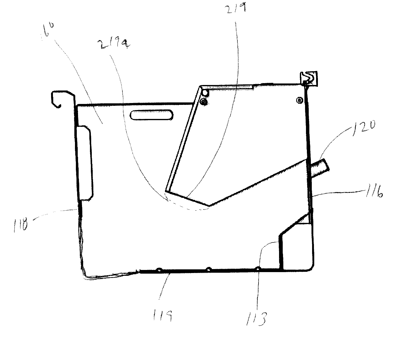
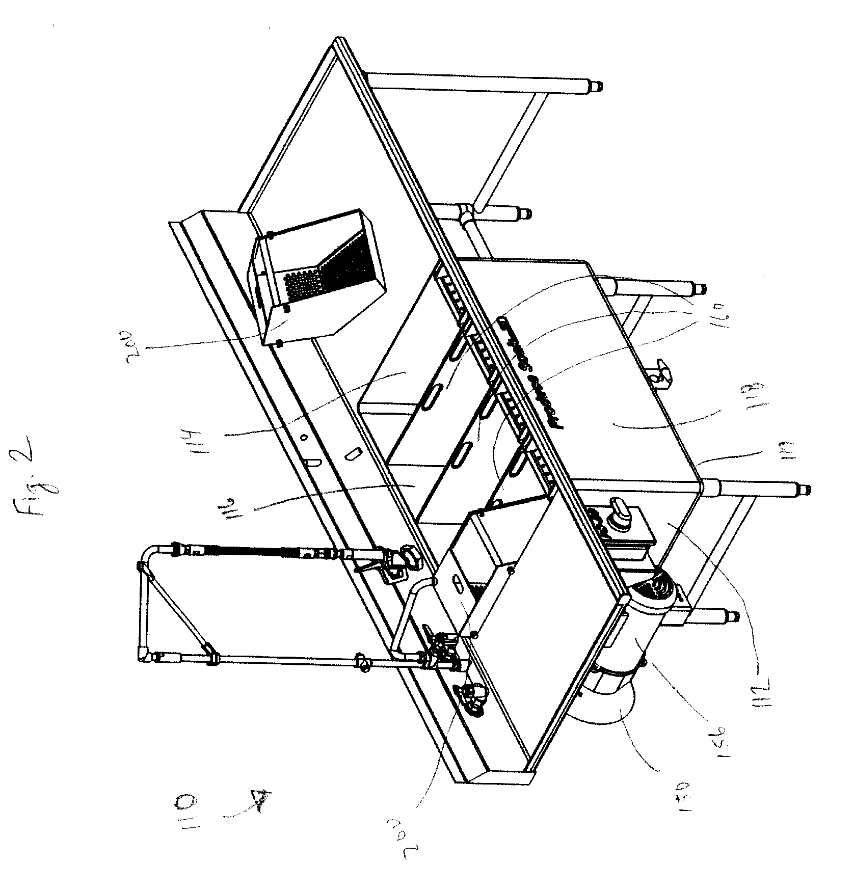
[0025]Referring to FIGS. 2 through 5, a preferred embodiment of a washing machine of the instant invention is shown, which is particularly useful for washing vegetables. Washing machine 110 includes a wash tank including end walls 112 and 114, rear side wall 116, front side wall 118 and bottom wall 119. A pump can be attached to either end wall; in the embodiment shown in FIG. 2, pump 150 is attached to left end wall 112. An impeller located w...


PUM


Abstract

A produce washer and method of washing produce or other items in a continuous motion washing machine is provided. The produce washer includes a basket, or other collector, that is positioned within a portion of the fluid flow path and sized and shaped to intercept items from a the fluid flow path while at the same time allowing the fluid to continue to flow through the collector generally in the same circulatory flow path created by the washing machine.

Description

CROSS-REFERENCE TO RELATED APPLICATIONS[0001]This application claims priority pursuant to 35 U.S.C. 119(e) to co-pending U.S. Provisional Patent Application Ser. No. 61 / 228,007, filed Jul. 23, 2009, the entire disclosure of which is incorporated herein by reference.FIELD OF THE INVENTION[0002]The present invention relates to a produce washer and methods of washing produce or other items. More particularly, the present invention relates to a produce washer and methods of washing produce or other items in a continuous motion washing machine.BACKGROUND OF THE INVENTION[0003]Continuous motion pot and pan washing machines, of the type used in restaurants, institutions and other eating facilities often involve a large wash tank or basin in which wash fluid is circulated to provide a rolling wash action for the pots and pans. One such machine is described in U.S. Pat. No. 4,773,436 issued to Cantrell et al., the entire disclosure of which is incorporated herein by reference. The machine of...

Claims


Application Information

Patent Timeline
Patent Type & Authority Applications(United States)
IPC IPC(8): A23N12/02B08B3/02B08B3/04
CPCA47L15/501A47L15/08A23N12/02
Inventor CANTRELL, JOHNCHURCHILL, MARK
Owner UNIFIED BRANDS
Why Eureka
Try Eureka