Safety latching lifting hook

a safety latching and lifting hook technology, applied in the direction of hook fasteners, load-engaging elements, fastening means, etc., can solve the problems of allowing the load to be released from the hook prematurely, and current lifting hook strategies have only limited success, so as to increase the safety factor, the effect of being safe and easy to us

Active Publication Date: 2011-07-21
PEMCO OF NEW MEXICO
View PDF10 Cites 30 Cited by
  • Summary
  • Abstract
  • Description
  • Claims
  • Application Information

AI Technical Summary

Benefits of technology

[0011]The safety latching lifting hook was originally designed and developed to provide the safest and easiest means of picking up and laying down tubing pipe for the well service industry. The design can readily be applied to other ‘hooking’ devices to provide the safety features developed specifically for the safety latching lifting pipe hook. The design of the elongated and enclosed ‘hook area’ increases the safety factor by affording additional protection for the operator's hand and acts as a constrained entrance and exit path for the pipe. The ‘hook area’ or pipe rest area has its center of gravity directly below and aligned with the pipe hook handle, which assists in keeping the pipe from swinging back into the operator. The spring loaded latch allows the pipe to be ‘hooked’ or loaded into the pipe hook without having to press the trigger to retract the latch or to release the trigger to release the latch. When loading the hook, the pipe pushes the latch back into the latch's recessed pocket allowing the pipe to move into the ‘hook area’, then the latch springs back against the latch stop securing the pipe within the hook. The typical hook with a spring activated latch (most commonly used on overhead hoist hooks) allows the lifting cable (chain, lifting straps, etc) to push the latch out of the way allowing the cable to move into the hook area. The spring activated latch then returns to rest against the hook stop. The operator's fingers have to manually move the spring activated latch out of the way and hold the latch until the cable is removed, which keeps the operator's fingers and hand(s) in harms way when unhooking. The Safety Latching Lifting Ho

Problems solved by technology

Current lifting hook strategies have had only limited success.
The trigger guard also protects the trigger from being hit

Method used


Image

  • Safety latching lifting hook
  • Safety latching lifting hook
  • Safety latching lifting hook

Examples


Embodiment Construction

[0022]Disclosed herein is a mechanical hook device. The numerous innovative teachings of the present invention will be described with particular reference to several embodiments (by way of example, and not of limitation).

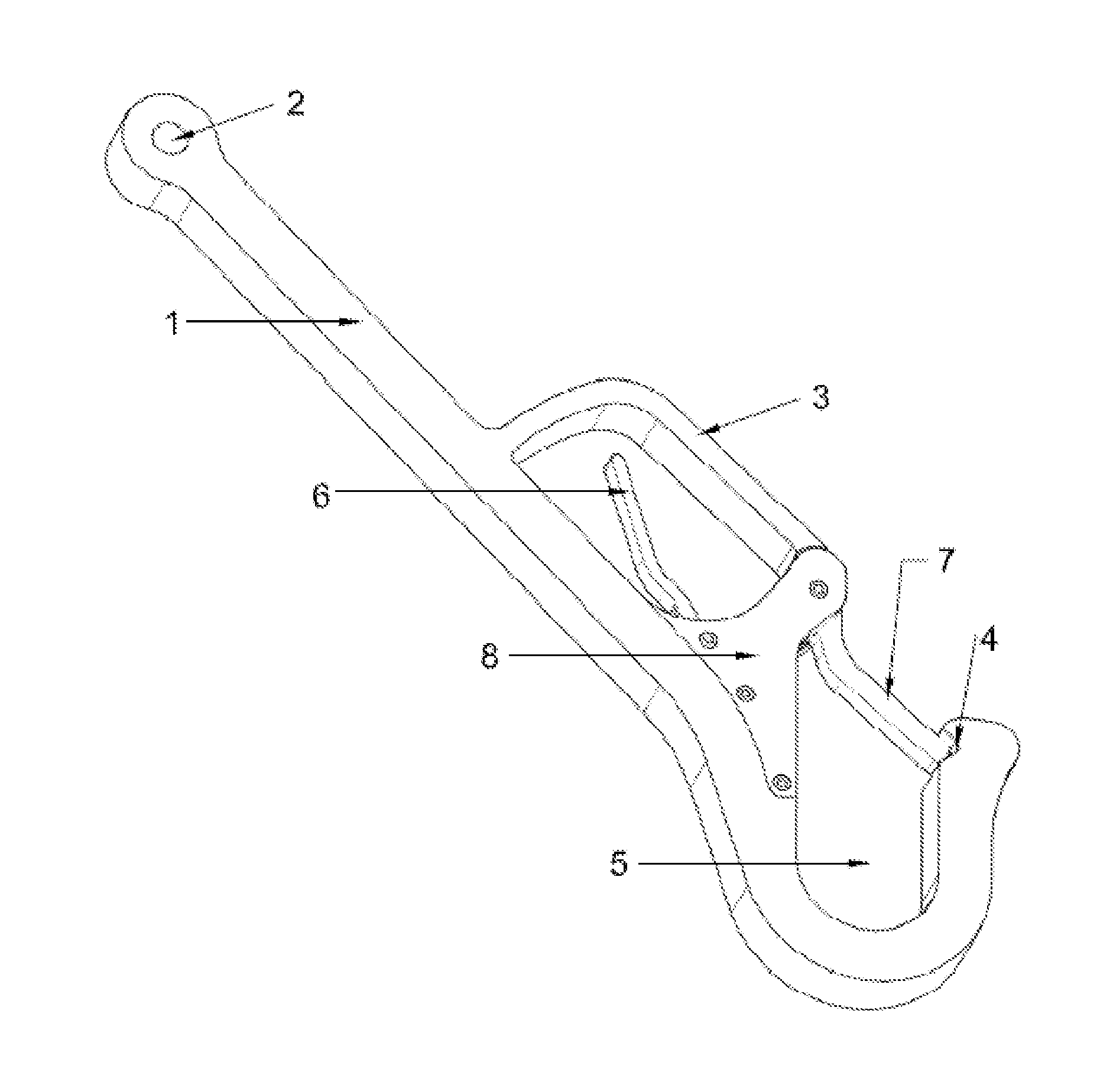
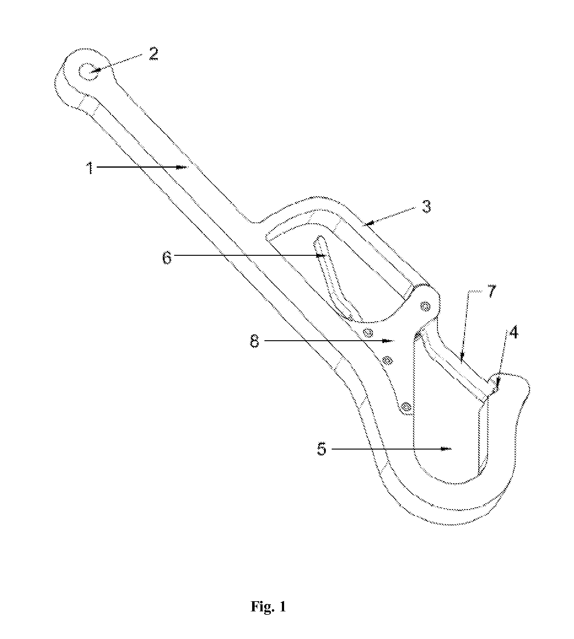
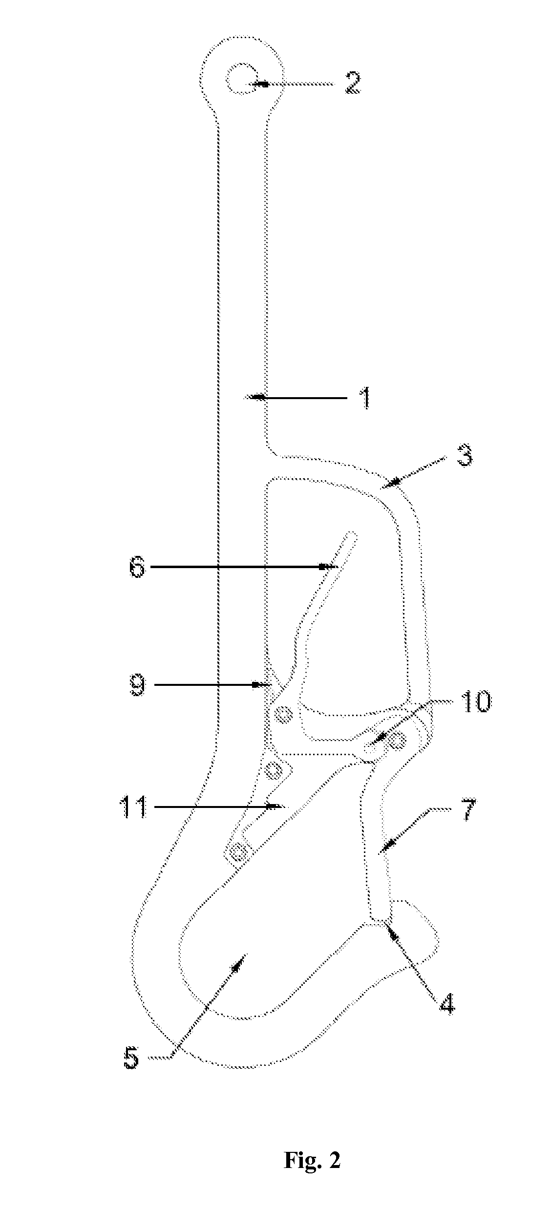
[0023]The hook type assembly in accordance with the present disclosure is shown in FIG. 1 and represents the pipe hook design with the main body 1 currently being cut out of a steel plate. A wire rope line is connected to the pipe hook at the attachment point 2 with a clevis or other attachment means. The wire rope line is utilized to raise, lower and transport the pipe to its required position. The hook design provides for the latch 7 to be held against the hook stop 4 by a torsion spring which keeps the pipe secured in the hook area 5 which is pipe size specific. The trigger 6 retracts the latch 7 allowing the pipe to be loaded (hooked) into the hook area 5, or to be released (unhooked) from the hook area 5. The trigger 6 is protected by the trigger guard 3 which ...


PUM


Abstract

The invention relates to a novel hook design which provides additional safety features to reduce the potential for accidents and provides additional protection to the operator. The invention may be applied to overhead hoist hooks, chain hooks, wire line hooks, and many other hooks. The safety design features include a spring activated trigger and latch mechanism, a latch stop, a trigger guard, and a trigger lock mechanism which may or may not utilize a spring to activate it. The safety latching lifting hook provides for ease of connection (hooking) and ease of release (unhooking) with a trigger guard to protect the operator's hand and the trigger latch mechanism.

Description

CROSS-REFERENCE TO RELATED APPLICATIONS[0001]This application claims the benefit under Title 35 United States Code §119(e) of U.S. Provisional Patent Application Ser. No. 61 / 336,331; Filed: Jan. 21, 2010, the full disclosure of which is incorporated herein by reference.STATEMENT REGARDING FEDERALLY SPONSORED RESEARCH OR DEVELOPMENT[0002]Not applicableTHE NAMES OF THE PARTIES TO A JOINT RESEARCH AGREEMENT[0003]Not applicableINCORPORATING-BY-REFERENCE OF MATERIAL SUBMITTED ON A COMPACT DISC[0004]Not applicableSEQUENCE LISTING[0005]Not applicableFIELD OF THE INVENTION[0006]The present invention relates to lifting hook devices. More specifically, the present invention relates to hooking devices used for lifting tubes and pipes and by extension the application may be extended to many types of hooking devices.BACKGROUND OF THE INVENTION[0007]Without limiting the scope of the disclosed invention, the background is described in connection with a novel hook device used for lifting tubes and ...

Claims


Application Information

Patent Timeline
IPC IPC(8): B66C1/36
CPCY10T24/45366B66C1/36F16B45/028F16B45/026
Inventor BUIE, GARRY ALANGANAWAY, BILLY RAYWILSON, GARRY ANTHONY
Owner PEMCO OF NEW MEXICO
Why Eureka
Try Eureka