
Control method for an inkjet printer, and an inkjet printer

Inactive Publication Date: 2011-07-21
SEIKO EPSON CORP
View PDF6 Cites 2 Cited by
  • Summary
  • Abstract
  • Description
  • Claims
  • Application Information

AI Technical Summary

Benefits of technology

[0014]The invention cleans plural inkjet heads sequentially from the n-th inkjet head, which is on the home position side end of the row of inkjet heads, before printing starts, and returns the inkjet heads 1 to n to the same positions as when waiting at the home position. As a result, there is no need to move the inkjet head in the direction away from the printing area after cleaning the inkjet heads is finished, and then reverse direction and move the inkjet head back to the printing area for printing, and the inkjet heads 1 to n can therefore be immediately moved to the printing area and printing can start. A plurality of inkjet heads can thus be cleaned efficiently before printing starts using a maintenance head cap disposed in one location without delaying the start of printing.

Problems solved by technology

The nozzles of an inkjet head used in an inkjet printer can become clogged as a result of an increase in the viscosity of ink left inside the nozzles, resulting in the clogged nozzles being unable to discharge a sufficient volume of ink.
If printing is attempted using an inkjet head in which some nozzles are clogged, dots may be dropped or poorly formed and print quality drops accordingly.
The suction mechanism therefore requires more suction channels than when there is only one maintenance head cap, and size and cost both increase because a motor with a strong suction force must be provided.
If the inkjet heads are not flushed in the appropriate order before printing starts in this configuration, wasted motion is created in the movement of the head carriage.
More specifically, the start of printing will be delayed if the inkjet head is not appropriately flushed before printing starts, and printer throughput will drop.

Method used


Image

  • Control method for an inkjet printer, and an inkjet printer
  • Control method for an inkjet printer, and an inkjet printer
  • Control method for an inkjet printer, and an inkjet printer

Examples


Embodiment Construction

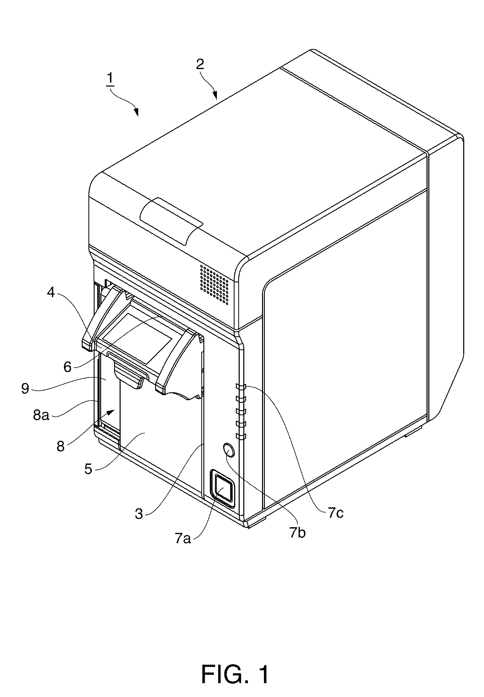
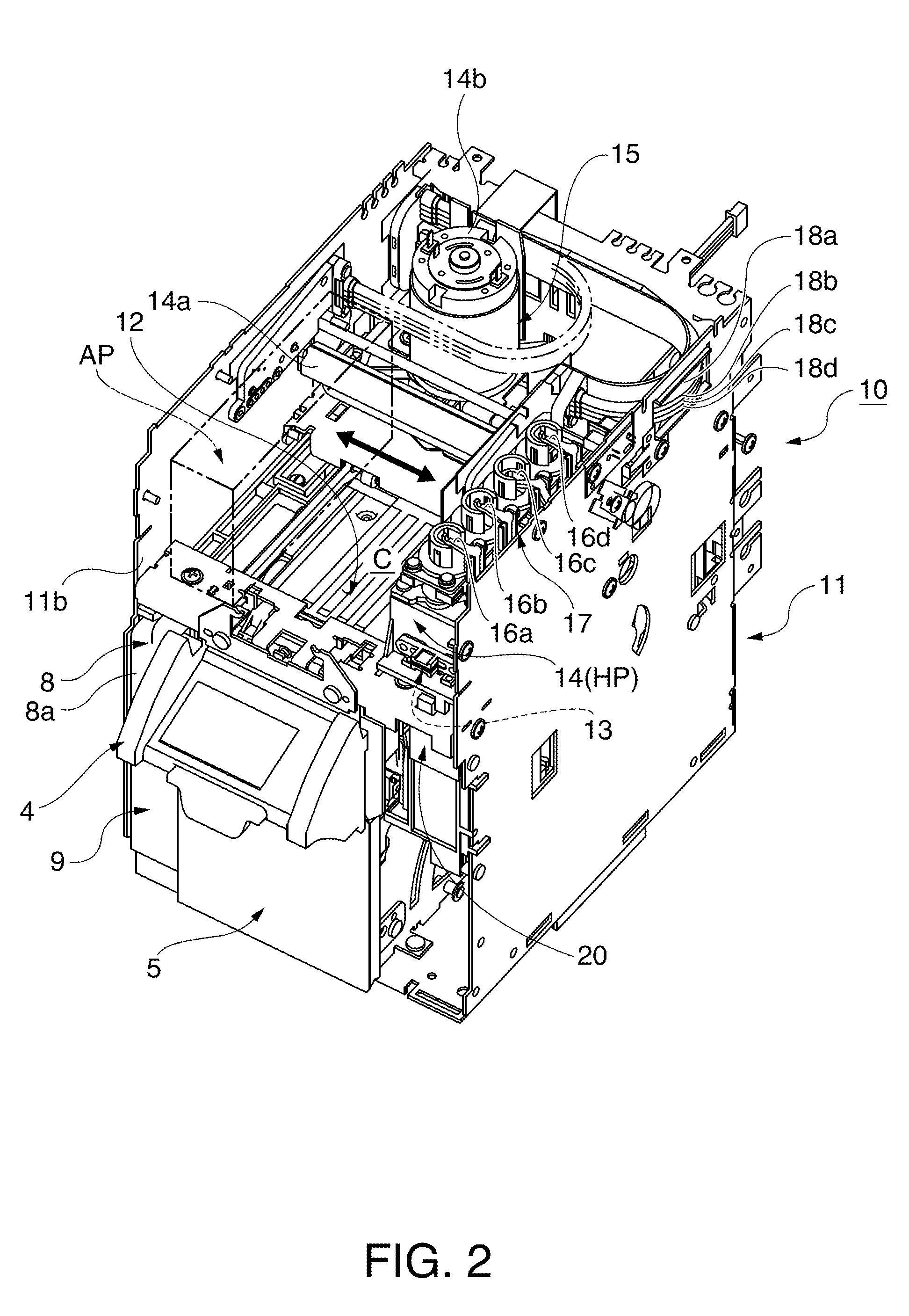
[0023]An inkjet printer according to a preferred embodiment of the invention is described below with reference to the accompanying figures.

[0024]General Configuration of an Inkjet Printer

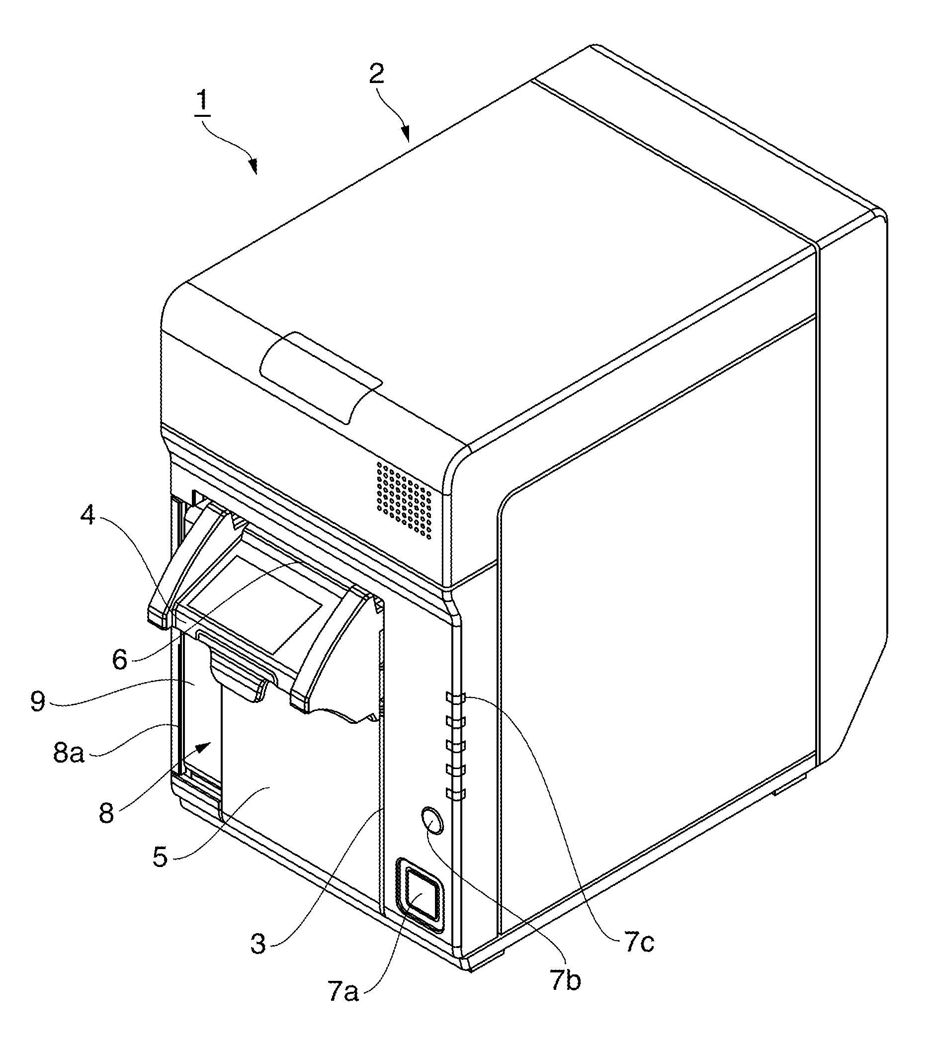
[0025]FIG. 1 is an external oblique view of an inkjet printer. The inkjet printer 1 prints in color on a continuous web of recording paper delivered from a paper roll using plural different colors of ink, and has a generally box-shaped printer case 2 with an opening 3 for loading roll paper formed in the front center part of the printer case 2. The opening 3 is closed by an access cover 5 to which a recording paper discharge guide 4 is disposed at the top. A recording paper exit 6 is formed between the recording paper discharge guide 4 and the top edge part of the opening 3 in the printer case 2. When a lock mechanism not shown is released and the recording paper discharge guide 4 is pulled forward by hand, the access cover 5 can pivot forward at the bottom end thereof from the closed position shown...


PUM


Abstract

An inkjet printer can desirably clean two inkjet heads mounted on a head carriage before printing starts. The inkjet printer 1 has first and second inkjet heads 13A and 13B mounted on a head carriage 14. Before printing starts, the inkjet printer moves the head carriage 14 from a home position HP to a shift position SP so that the second inkjet head 13B, which is closest to the home position HP, is opposite a maintenance head cap 22 with an ink absorption capability and cleans the inkjet head. The head carriage 14 is then returned to the home position HP so that the first inkjet head 13A is opposite the maintenance head cap 22 and cleans the inkjet head. The head carriage 14 then moves to the printing area C side and printing starts.

Description

BACKGROUND[0001]1. Technical Field[0002]The present invention relates to an inkjet printer and to a control method for an inkjet printer that executes a cleaning process to discharge ink droplets from the nozzles of plural inkjet heads that are carried on a head carriage in order to prevent the plural nozzles of the inkjet head from clogging.[0003]2. Related Art[0004]The nozzles of an inkjet head used in an inkjet printer can become clogged as a result of an increase in the viscosity of ink left inside the nozzles, resulting in the clogged nozzles being unable to discharge a sufficient volume of ink. If printing is attempted using an inkjet head in which some nozzles are clogged, dots may be dropped or poorly formed and print quality drops accordingly. Inkjet printers therefore regularly or at specified times move the carriage that carries the inkjet head to a home position removed from the printing area so that the nozzle surface of the inkjet head is opposite a head cap with an in...

Claims


Application Information

Patent Timeline
IPC IPC(8): B41J2/165
CPCB41J2/1652B41J2/16508B41J2/16505
Inventor KURODA, KIYOMI
Owner SEIKO EPSON CORP
Learn More