Optical tomographic imaging apparatus and control method for the same

Inactive Publication Date: 2011-07-21
CANON KK
View PDF13 Cites 16 Cited by
  • Summary
  • Abstract
  • Description
  • Claims
  • Application Information

AI Technical Summary

Benefits of technology

[0009]As described above, a measurement of a conventional OCT apparatus for ophthalmology using

Problems solved by technology

Such a measurement with a wide angle of view takes much time to measure, resulting in a position shift

Method used


Image

  • Optical tomographic imaging apparatus and control method for the same
  • Optical tomographic imaging apparatus and control method for the same
  • Optical tomographic imaging apparatus and control method for the same

Examples


embodiment 1

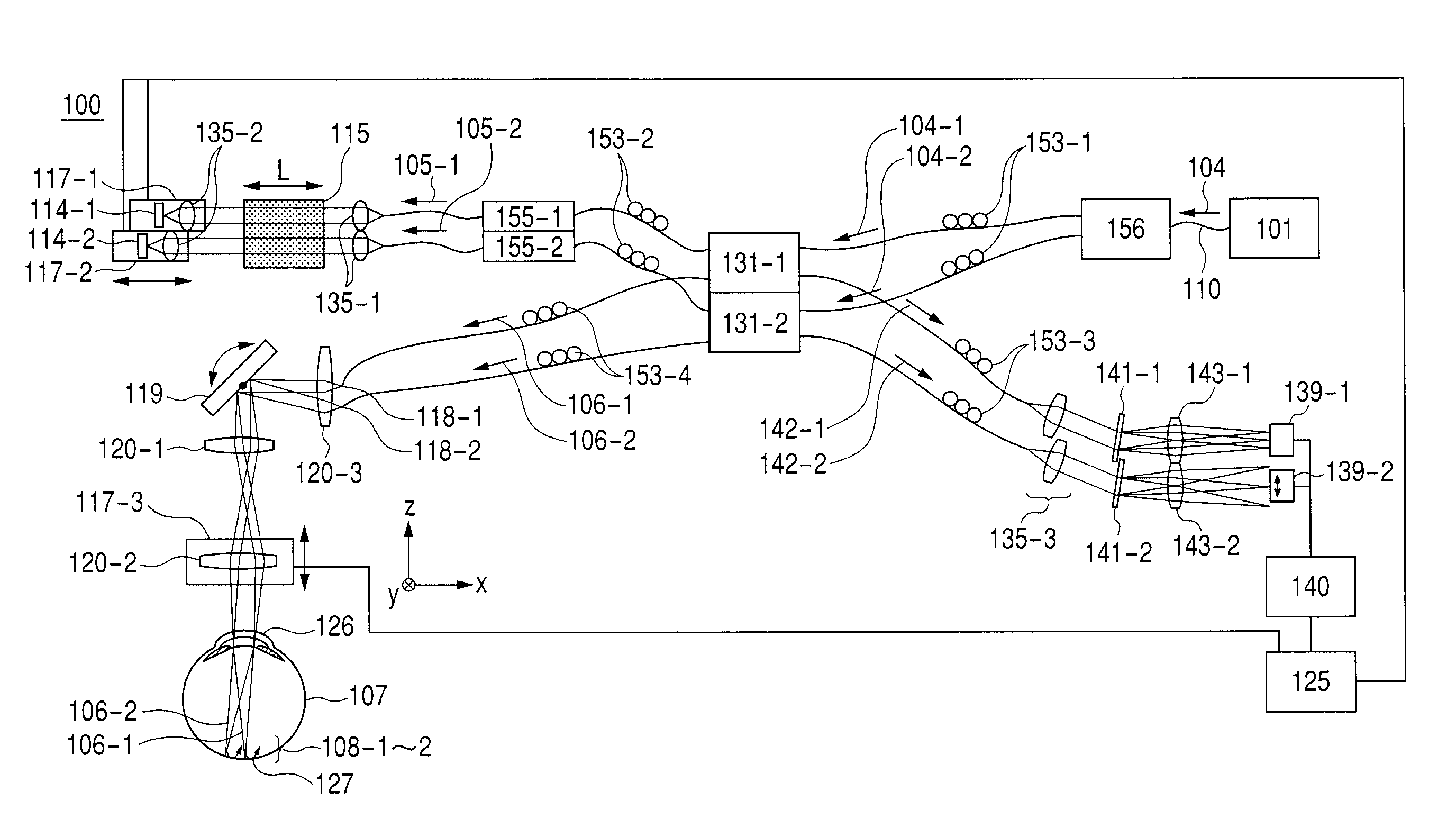
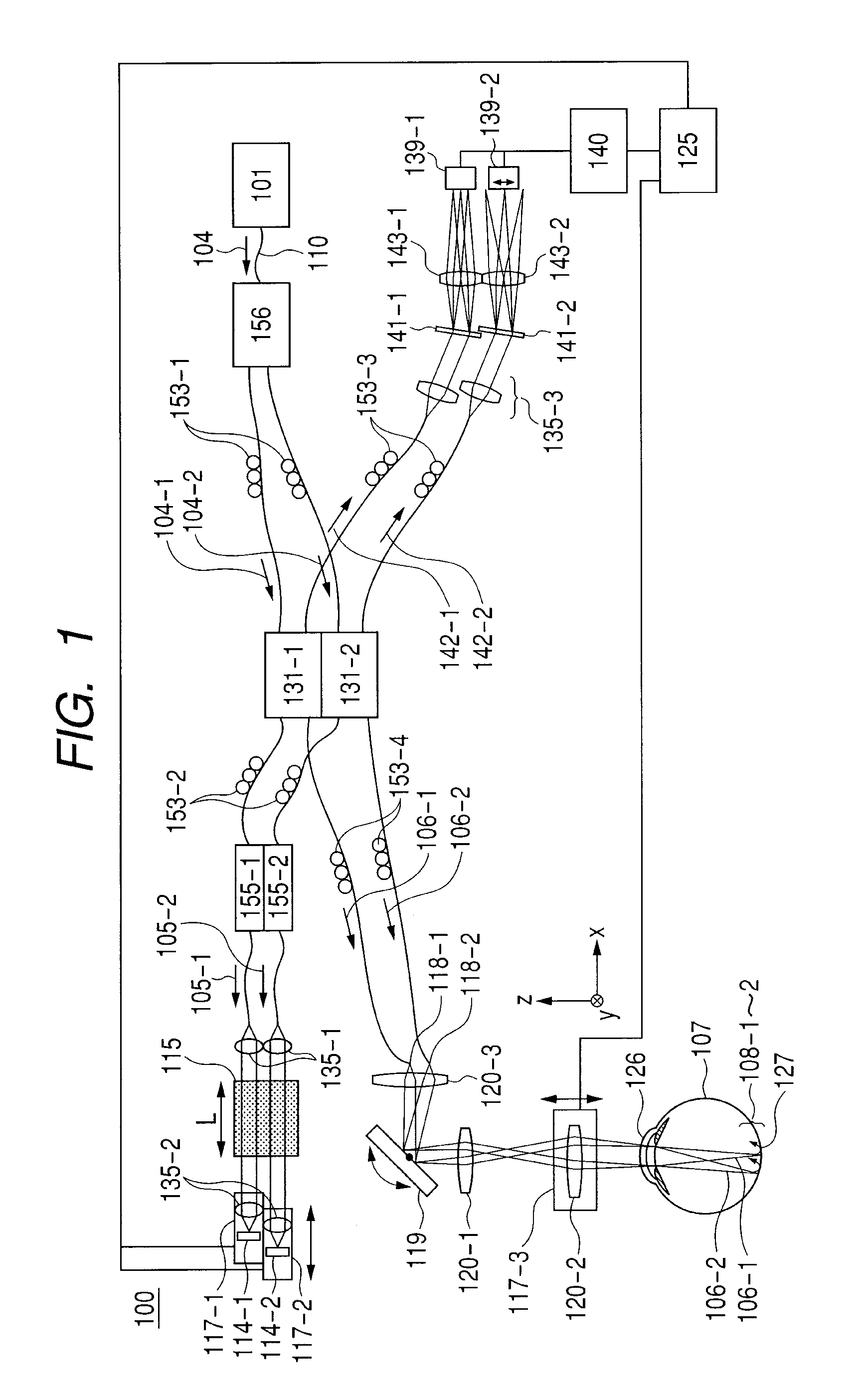
[0026]In a first exemplary embodiment, an optical tomographic imaging apparatus (OCT apparatus) to which the present invention is applied is described with reference to FIG. 1.

[0027]An OCT apparatus 100 in the exemplary embodiment, as illustrated in FIG. 1, is a Michelson interferometer as a whole.

[0028]That is, light emitted from a light source is split into a measuring beam and a reference beam.

[0029]Then, a configuration includes an OCT system in which the measuring beam has a plurality of measurement light paths, and a return beam formed of a plurality of measuring beams and a reference beam through a reference light path are combined with each other for light interference to produce a plurality of combined beams, and by using the plurality of combined beams, a tomographic image of an object is imaged.

[0030]Specifically, as illustrated in FIG. 1, an emitted beam 104 emitted from a light source 101 is directed through a single-mode fiber 110 to enter an optical coupler 156, and s...

embodiment 2

[0150]In the first exemplary embodiment, the focal length of the focusing lenses 143-1 and 143-2 is varied to measure the right and left eye. On the contrary, a second exemplary embodiment describes an example of a configuration in which a grating pitch of the transmission diffraction gratings 141-1 and 141-2 is varied.

[0151]The term “pitch” is the amount associated with the width of a pattern periodically carved in a diffraction grating, and shown by the number of patterns carved per mm ( / mm).

[0152]An OCT apparatus 100 is arranged similar to the first exemplary embodiment, and description thereof is omitted.

[0153]FIGS. 5A, 5B, 5C and 5D illustrate schematic views for illustrating imaging by a line camera in which Δy is set at a different state.

[0154]The arrows in FIGS. 5B and 5D show the spectral width on the line camera, and colored portions are the line cameras.

[0155]Also, FIGS. 5A and 5B illustrate the case where the transmission diffraction gratings 141-1 and 141-2 have a wide ...

embodiment 3

[0169]In the first exemplary embodiment, the optical system is changed responsive to changing the eye side to side. On the contrary, a third exemplary embodiment describes an example of a configuration in which an optical system for replacement is provided in advance.

[0170]That is, in the third exemplary embodiment, an OCT apparatus includes 3 light paths having a third light path, in addition to the first light path and the second light path, for directing 3 light path light beams (the first and second measuring beam, and a third measuring beam), and each of the light paths is configured as follows:

[0171]the first light path: for the optic disc (left eye)

[0172]the second light path: for the macula (left eye and right eye)

[0173]the third light path: for the optic disc (right eye).

[0174]FIG. 6 illustrates a configuration of a measuring system in the exemplary embodiment. This measuring system differs in that each of the components is added corresponding to the increase in the number ...


PUM


Abstract

There is provided an optical tomographic imaging apparatus for imaging a tomographic image capable of setting characteristics of an optical system to accommodate to different positions on an object. The apparatus using an OCT system, includes: a scanning device for scanning measuring beams, an irradiating device for irradiating a different irradiation area on the object with the measuring beams scanned by the scanning device, an adjusting device for adjusting an irradiation position on the object of the measuring beams irradiated by the irradiating device, and a detecting device for detecting each combined beam produced from light interference between each of the return beams and the reference beams, characterized in that: the detecting device includes spectroscopy devices and a sensor, and a spectral width of the combined beam acquired with the sensor through the spectroscopy devices is set at a different spectral width by the spectroscopy devices.

Description

TECHNICAL FIELD[0001]The present invention relates to an optical tomographic imaging apparatus and a control method for the same, and particularly to an optical tomographic imaging apparatus used for ophthalmologic diagnosis, and a control method for the same.BACKGROUND ART[0002]Adopting Optical Coherence Tomography (OCT) allows a tomographic image of an object (particularly, the fundus) to be imaged with a high resolution.[0003]Particularly, OCT of the Fourier-domain system has a configuration capable of scanning at a time in the depth direction.[0004]An optical tomographic imaging apparatus according to such Optical Coherence Tomography is hereinafter called “an OCT apparatus”.[0005]An OCT apparatus for ophthalmology may include an important measured position such as the macula and the optic disc. Conventionally, many apparatuses for diagnosing the eye disease may measure these two positions with an OCT apparatus using a single beam.[0006]For such conventional OCT apparatus for op...

Claims


Application Information

Patent Timeline
IPC IPC(8): A61B3/12G01J3/45G01N21/17G01N21/35G01N21/359
CPCA61B3/102G01N21/4795A61B3/1225
Inventor YOSHIDA, HIROFUMIUTSUNOMIYA, NORIHIKO
Owner CANON KK
Why Eureka
Try Eureka