
Powering method and powering device of fuel cell

Inactive Publication Date: 2011-07-21
YOUNG GREEN ENERGY
View PDF0 Cites 2 Cited by
  • Summary
  • Abstract
  • Description
  • Claims
  • Application Information

AI Technical Summary

Benefits of technology

[0009]The invention is directed to a powering method and a powering device of a fuel cell having at least one of the following advantages; preventing hydrogen gas and electricity from wasting and being convenient in use.
[0010]Numerous features and advantages of the invention could be better understood by referring to the disclosure herein.
[0016]Based on the above embodiments, the embodiment of the invention has at least one of the following advantages. The fuel cartridge is divided into a plurality of fuel cells, in each of which chemical reaction could take place. Accordingly, the control unit could spontaneously select and trigger one or more of the fuel units based on the electric power required by the load or the electric quantity of the accumulator. Thereby, waste of the hydrogen gas and electricity could be reduced or prevented.

Problems solved by technology

Development and application of energy are always indispensable in our daily lives, while development and application of energy sources lead to increasing environmental destruction.
It could be learned from above that excessive fuel in the fuel cartridge is constantly supplied even though the secondary battery is fully charged.
The waste of fuel leads to incomplete utilization of the fuel supplied by the fuel cartridge.
Additionally, the hydrogen gas may not be properly processed, which is dangerous.
Moreover, when there is residual fuel in the fuel cartridge, a user oftentimes retrieves the fuel cartridge manually to prevent leakage of the hydrogen gas, which is inconvenient in use.

Method used


Image

  • Powering method and powering device of fuel cell
  • Powering method and powering device of fuel cell
  • Powering method and powering device of fuel cell

Examples


Embodiment Construction

[0022]It is to be understood that other embodiment may be utilized and structural changes may be made without departing from the scope of the invention. Also, it is to be understood that the phraseology and terminology used herein are for the purpose of description and should not be regarded as limiting. The use of “including,”“comprising,” or “having” and variations thereof herein is meant to encompass the items listed thereafter and equivalents thereof as well as additional items. Unless limited otherwise, the terms “connected,”“coupled,” and “mounted,” and variations thereof herein are used broadly and encompass direct and indirect connections, couplings, and mountings.

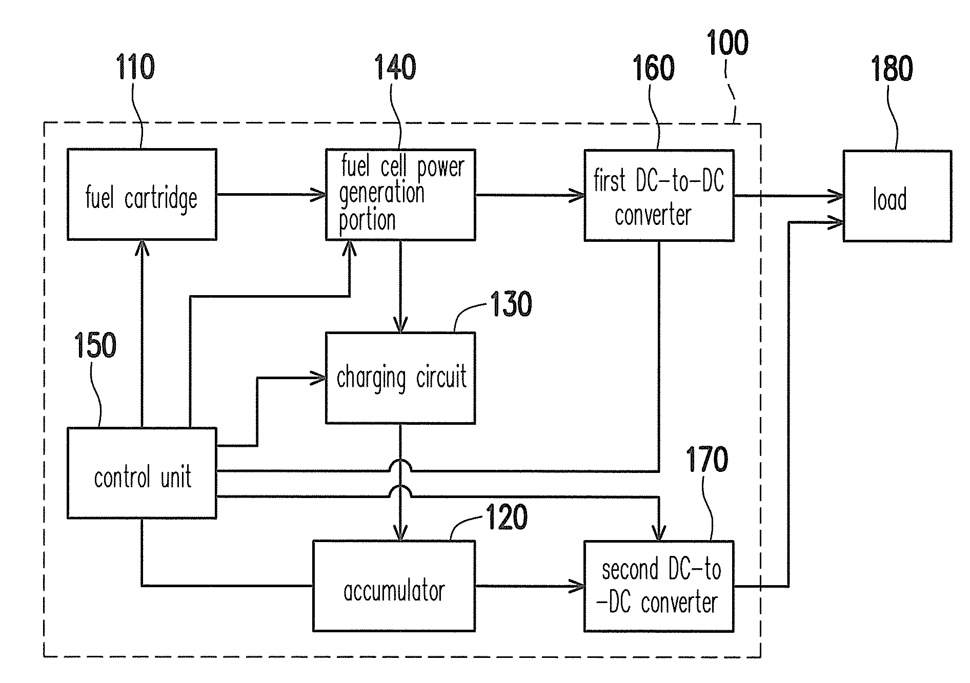
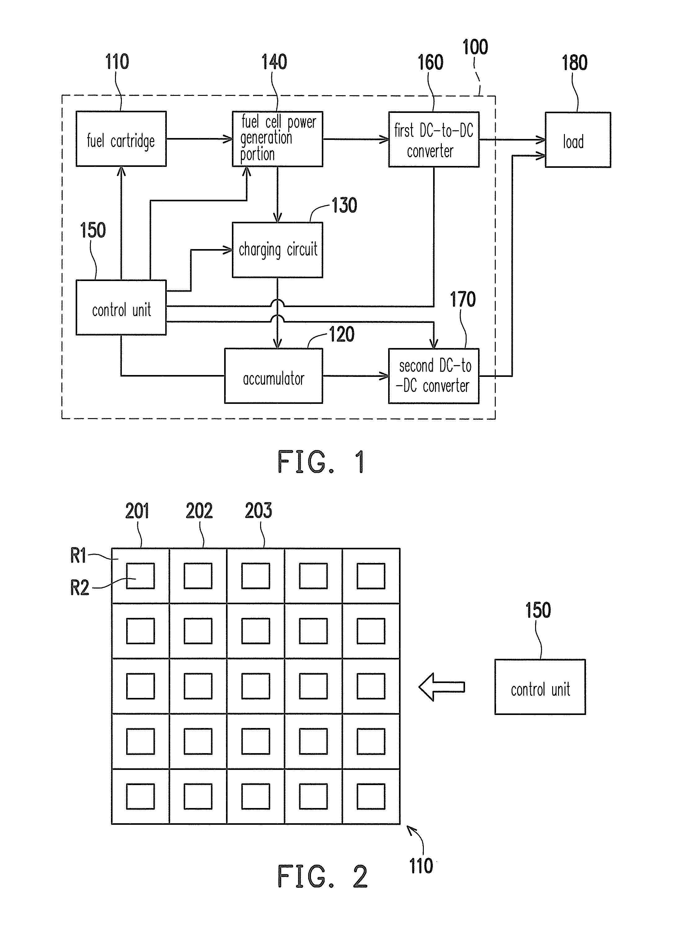
[0023]FIG. 1 is a block view illustrating a powering device 100 of a fuel cell according to an embodiment of the invention. As shown in FIG. 1, the powering device 100 of the fuel cell is capable of supplying electric power to a load 180. The powering device 100 of the fuel cell includes a fuel cartridge 110, an ac...


PUM


Abstract

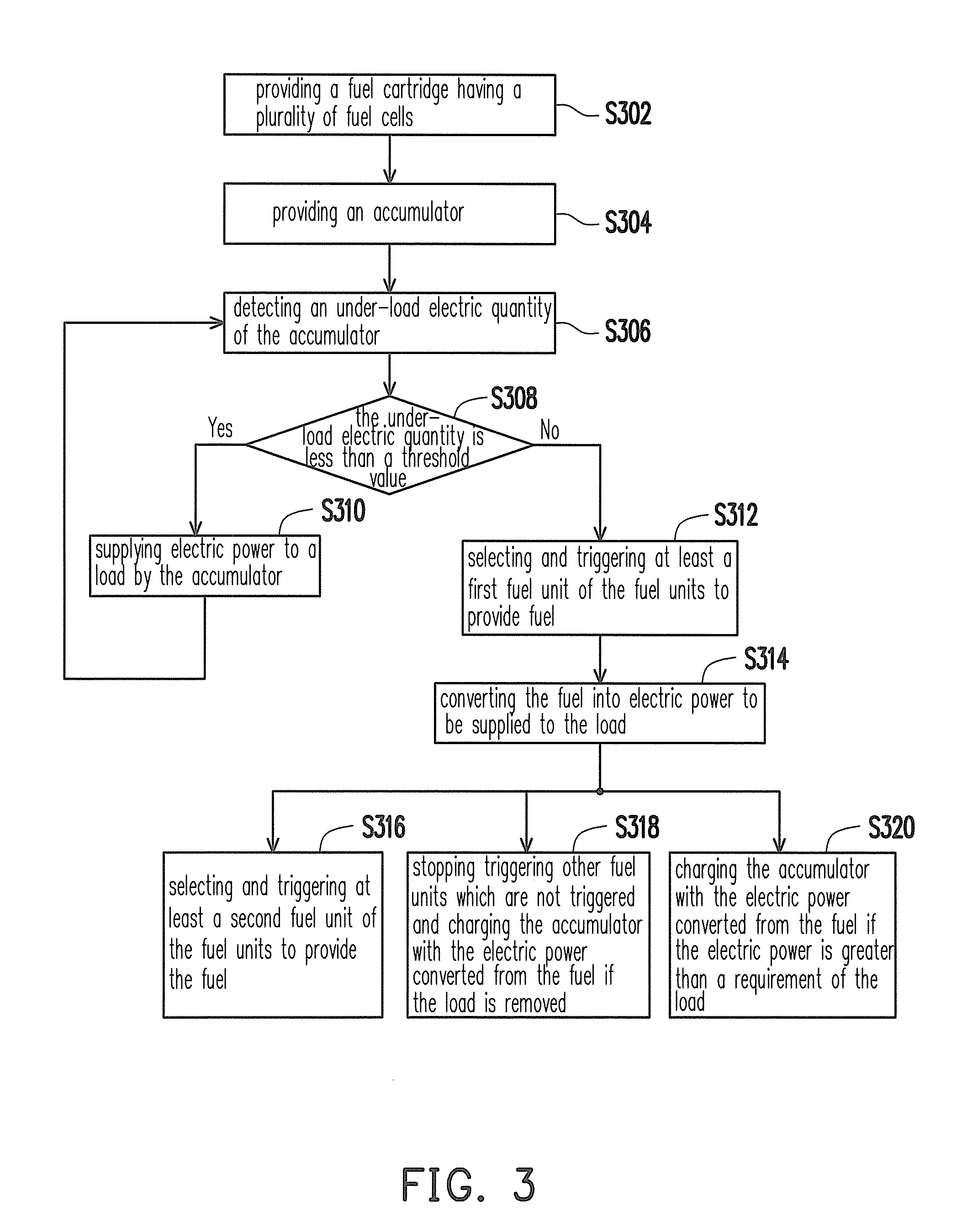
A powering method of a fuel cell includes following steps. A fuel cartridge including a plurality of fuel units and an accumulator is provided. An under-load electric quantity of the accumulator is detected. If the under-load electric quantity is less than a threshold, power is supplied by the accumulator to a load. If the under-load electric quantity is greater than the threshold, a first fuel unit of the fuel units is selected and triggered to provide fuel which converted into the power. If the fuel of the first fuel unit is not enough to supply the power to the load, a second fuel unit of the fuel units is selected and triggered to provide the fuel. If the load is removed, the other fuel units which are not yet triggered are not triggered, and the accumulator is charged with the power converted from the fuel.

Description

CROSS-REFERENCE TO RELATED APPLICATION[0001]This application claims the priority benefit of P.R. China application serial no. 201010002985.3, filed on Jan. 15, 2010. The entirety the above-mentioned patent application is hereby incorporated by reference herein and made a part of specification.BACKGROUND OF THE INVENTION[0002]1. Field of the Invention[0003]The invention relates to a fuel cell. More particularly, the invention relates to a powering method and a powering device of a fuel cell.[0004]2. Description of Related Art[0005]Development and application of energy are always indispensable in our daily lives, while development and application of energy sources lead to increasing environmental destruction. Fuel cell-based power generation characterized by high efficiency, low noise, and non-pollution complies with the energy-saving trend.[0006]The most commonly known fuel cell basically has a fuel cartridge, a fuel cell power generation portion, and a secondary battery. The fuel ce...

Claims


Application Information

Patent Timeline
IPC IPC(8): H01M8/06
CPCH01M8/04089H01M8/04626H01M8/04753Y02E60/50H01M8/04947H01M16/006H01M8/0494Y02E60/10
Inventor HUNG, KUO-TAIWANG, CHENG
Owner YOUNG GREEN ENERGY
Learn More