
Apparatus and methodology for calibration of a gyroscope and a compass included in a handheld device

a handheld device and compass technology, applied in the field of handheld devices, can solve the problems of continuous drift, difficult to determine the magnetic north pole of the earth, and bias errors in both compasses and gyroscopes

Active Publication Date: 2011-07-21
INVENSENSE
View PDF13 Cites 90 Cited by
  • Summary
  • Abstract
  • Description
  • Claims
  • Application Information

AI Technical Summary

Benefits of technology

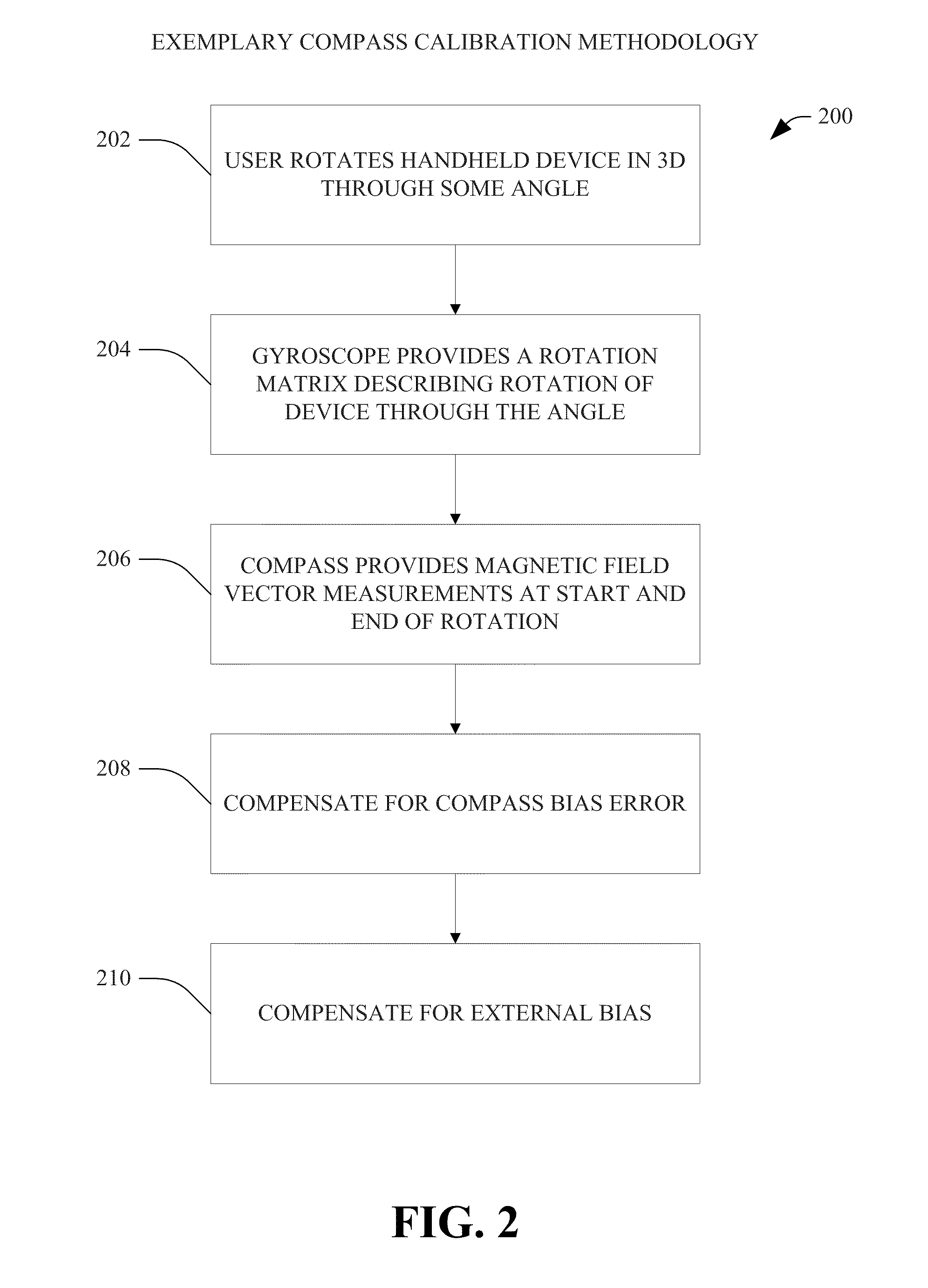
[0008]The present invention relates to novel and efficient computer system and methodology for correcting biases for gyroscopes and accelerometers and compasses included in handheld devices including motion sensing applications, for example, wireless phones, video gaming systems, navigational devices and cameras. According to one aspect of the present invention, a handheld device is rotated through an angle. The rotation information received from the gyroscope is compared with the rotation information received from the compass, and the result of the comparison is used to determine the compass bias. An advantage of the present invention is that the compass bias can be determined by causing only a small movement of the handheld device. In conventional systems, which do not use the gyroscope data to determine the compass bias, a much larger trajectory of the handheld device is required to determine the compass bias.
[0009]According to another aspect of the present invention, rotation information received from a gyroscope, a compass and an accelerometer is used to determine a quaternion based angular velocity (AV) term. The quaternion AV term is compared with the gyro data to determine the gyro bias error. In situations in which the compass data and / or the gyroscope data are unreliable, quaternion based AV term is not determined. In those situations, a quaternion based AV term stored in a memory, which was previously determined when the compass and accelerometer data were reliable, is used for estimating a gyroscope bias This term can be used to estimate the gyro bias continuously, even when the device is not completely stationary or temperature is changing.
[0010]According to yet another aspect of the present invention, the handheld device is placed in a non-factory setting in which the handheld device is not subject to a strong linear acceleration and the handheld device is not subject to a rapidly changing magnetic field. In that setting, when the temperature changes, gyroscope biases at various temperature values are measured and stored in a database. The database is then used to estimate the gyroscope bias in situations in which the accelerometer and / or the compass data are unreliable.

Problems solved by technology

Bias errors are associated with both compasses and gyroscopes.
The bias error in a compass makes it difficult to determine earth's magnetic North pole.
If the gyro bias offset is not corrected, it can result in a continuous drift.
Large bias errors are common in compasses due to the nature of low cost Hall sensor based compasses.
A problem with this method is that it requires the user to move the device having the compass in a complex trajectory (e.g. a figure eight) in order for this method to have enough information to converge.
However, at times the compass and / or the accelerometer data can become unreliable.
If, for example, the compass data becomes unreliable due to magnetic interference etc. or the accelerometer data becomes unreliable because of the presence of high linear accelerations, the compass data and / or the accelerometer data cannot be used.
In that case, any existing gyro bias error would be uncompensated and result in a continuous drift.

Method used


Image

  • Apparatus and methodology for calibration of a gyroscope and a compass included in a handheld device
  • Apparatus and methodology for calibration of a gyroscope and a compass included in a handheld device
  • Apparatus and methodology for calibration of a gyroscope and a compass included in a handheld device

Examples


Embodiment Construction

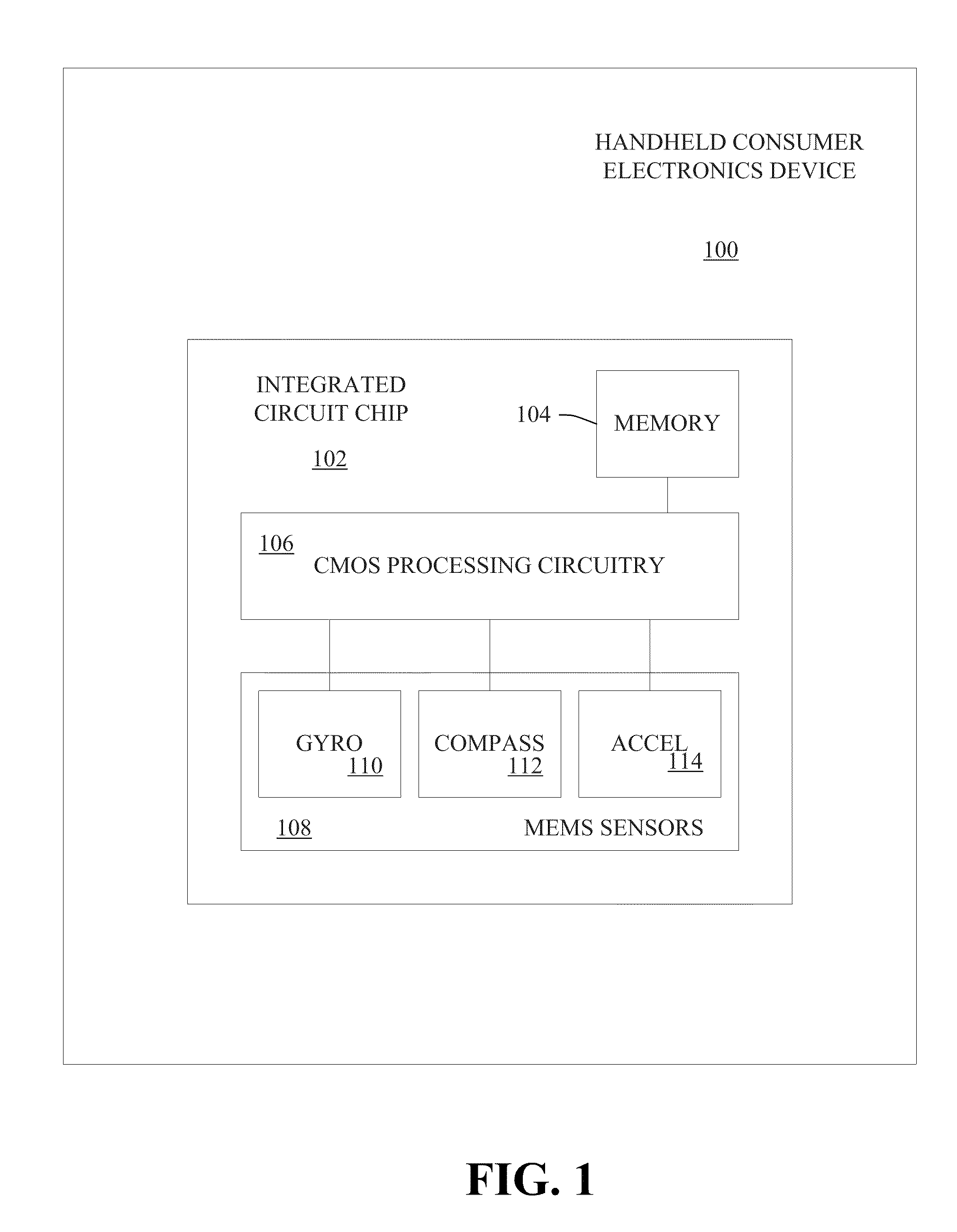
[0024]The present invention related to systems and techniques for calibrating gyroscopes and compasses incorporated in handheld consumer electronic devices including, for example, remote controllers, cameras and wireless navigational devices. The claimed subject matter is now described with reference to the drawings, wherein like reference numerals are used to refer to like elements throughout. In the following description, for purposes of explanation, numerous specific details and examples are set forth in order to provide a thorough understanding of the subject innovation. One of ordinary skill in the art will understand, however, that the subject innovation may be practiced without these specific details and is not limited by these specific details and examples. One of ordinary skill in the art will also appreciate that well-known structures and devices are shown in block diagram form in order to facilitate describing the claimed subject matter.

[0025]As used in this application, ...


PUM


Abstract

Novel techniques for estimating compass and gyroscope biases for handheld devices are disclosed. The handheld devices can include wireless phones, navigational devices and video gaming systems. The compass bias can be determined by causing a small movement of the handheld device and comparing the data obtained from the compass with the data obtained from the gyroscope. The gyroscope bias can be determined by obtaining a quaternion based angular velocity term of the handheld device when the accelerometer and compass data are reliable, and then comparing the angular velocity term to with the gyro data estimate the gyro bias. When the compass and / or the accelerometer data are unreliable, a previously determined quaternion angular velocity term is used, which was determined when the compass and the accelerometer were providing reliable data. The gyroscope bias can also be determined by measuring gyroscope biases at various temperatures in a non-factory setting, and storing that data in a memory, and using the data to estimate gyro biases when the accelerometer and / or the compass data are unreliable.

Description

FIELD OF THE INVENTION[0001]The present invention relates to handheld devices, for example, a video game controller or a handheld navigation device, and particularly to the calibration of a gyroscope and a compass included in a handheld device.BACKGROUND OF THE INVENTION[0002]Compasses and accelerometers are being used in commercial products, particularly in video gaming, automotive and navigational systems. InvenSense Inc., the assignee of the present invention, is a pioneer in the field of using a combination of gyroscopes, accelerometers and compasses in handheld commercial devices such as wireless phones, video gaming systems, cameras, user authentication devices and other devices in which motion sensing is done. An accelerometer is used for measuring linear acceleration, a compass is used for determining direction relative to the earth's magnetic pole, and a gyroscope is used for measuring or maintaining orientation based on the Coriolis Effect.[0003]Bias errors are associated ...

Claims


Application Information

Patent Timeline
Patent Type & Authority Applications(United States)
IPC IPC(8): G01C25/00G01C21/16G01C17/38G01P15/00G01C19/00G06F17/30
CPCG01C17/38G01C25/005G01C19/00
Inventor SACHS, DAVIDLIN, SHANG HUNG
Owner INVENSENSE
Learn More