Zero-Wall Clearance Linkage Mechanism for a High-Leg Seating Unit

a high-leg seating unit and linkage mechanism technology, applied in the field of motion upholstery furniture, can solve the problems of imposing constraints on upholstery designers, assembly limitations on certain design aspects utilized by furniture manufacturers, and unit linkage mechanisms that are relatively complex, and achieve the effect of convenient and cost-effectiv

Inactive Publication Date: 2011-07-28
L & P PROPERTY MANAGEMENT CO
View PDF18 Cites 44 Cited by
  • Summary
  • Abstract
  • Description
  • Claims
  • Application Information

AI Technical Summary

Benefits of technology

[0008]Generally, embodiments of the present invention seek to provide a simplified, compact linkage mechanism that can be adapted to essentially any type of seating unit. In particular embodiments, the present invention seeks to provide a linkage mechanism that can be assembled to a compact motor and that can be adapted to essentially any type of seating unit. In operation, the compact motor in concert with the linkage mechanism can achieve full movement of the seating unit between the closed, extended, and reclined positions. The compact motor may be employed in a proficient and cost-effective manner to adjust the linkage mechanism without creating interference or other disadvantages (e.g., preclusion of adaption to high-leg models) appearing in conventional designs that are inherent with automation.

Problems solved by technology

However, these seating units require relatively complex linkage mechanisms to afford this capability.
The complex linkage assemblies limit certain design aspects utilized by furniture manufacturers.
In one instance, these linkage assemblies impose constraints on an upholstery designer's use of multiple styling features concurrently on an adjustable seating unit.
For instance, these linkage assemblies are bulky and require seating units to incorporate space-saving features (connecting the linkage mechanisms to a base resting on the floor), thereby hiding the linkage assemblies below the seat when in the closed position.
But, these space-saving features preclude a furniture designer from providing the seating unit configured with arms that rest either directly or indirectly, via the support of high legs, on an underlying surface.
In another instance, these linkage assemblies impose constraints on incorporating a single motor for automating adjustment between the positions mentioned above, and require two or more motors to accomplish automation of each adjustment.

Method used


Image

  • Zero-Wall Clearance Linkage Mechanism for a High-Leg Seating Unit
  • Zero-Wall Clearance Linkage Mechanism for a High-Leg Seating Unit
  • Zero-Wall Clearance Linkage Mechanism for a High-Leg Seating Unit

Examples


Embodiment Construction

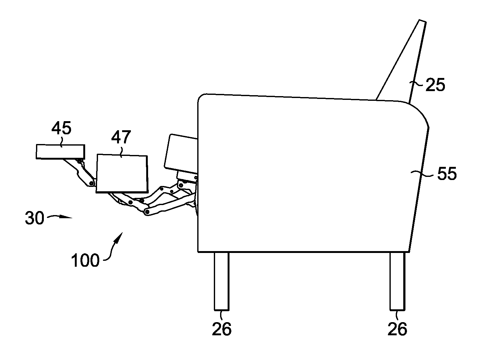
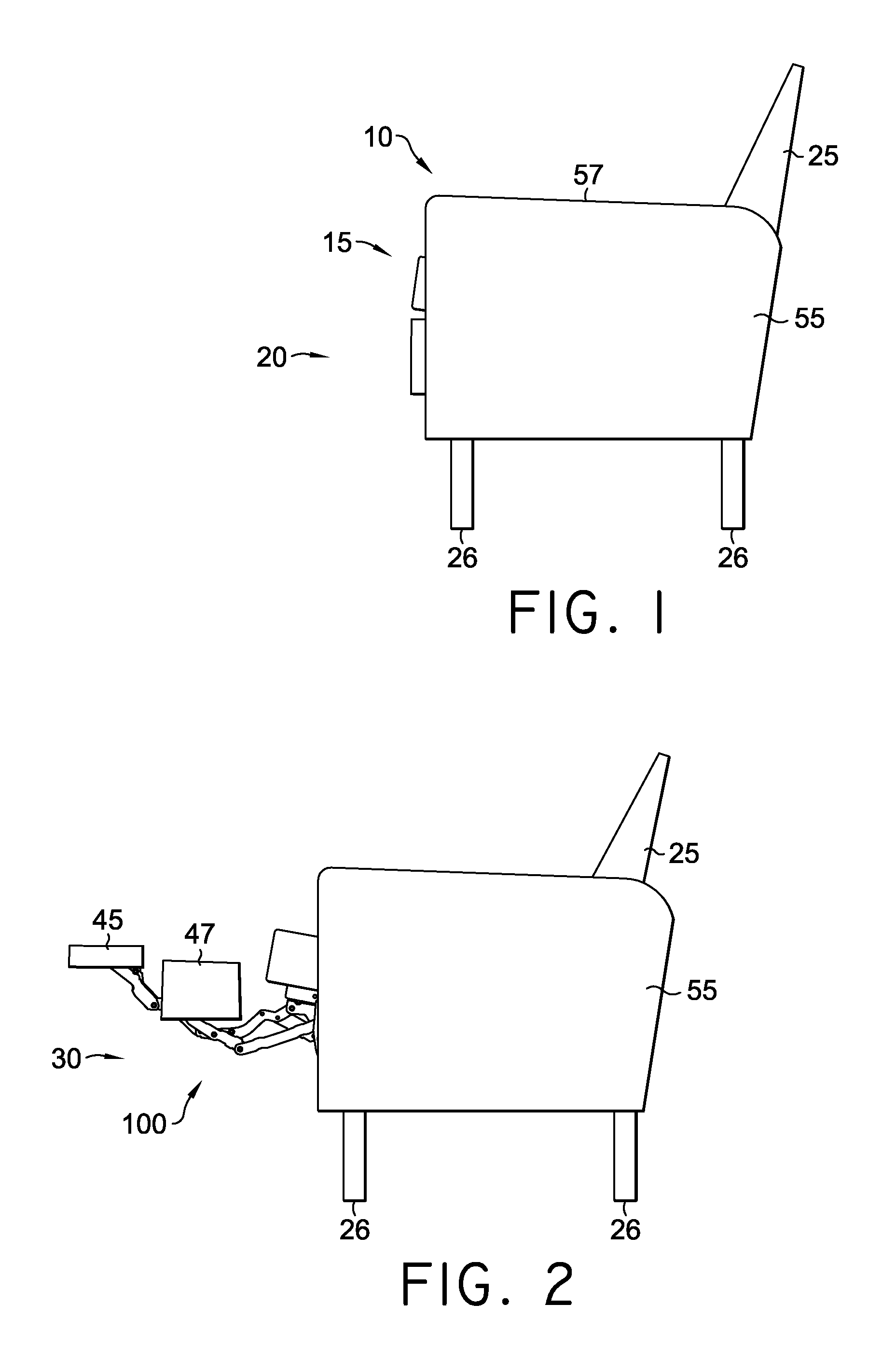
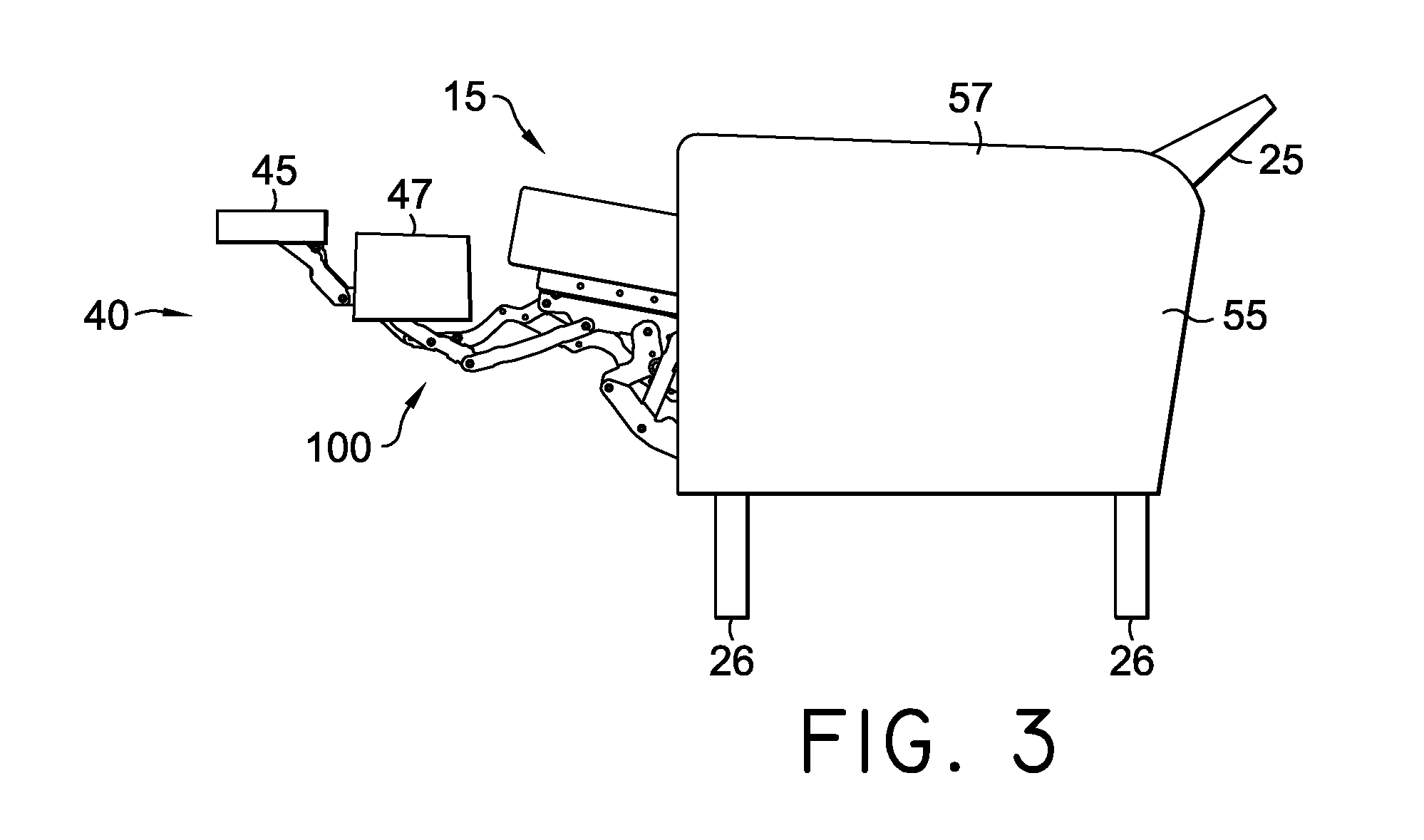
[0030]FIGS. 1-3 illustrate a seating unit 10. Seating unit 10 has a seat 15, a backrest 25, legs 26, a linkage mechanism 100, a first foot-support ottoman 45, a second foot-support ottoman 47, and a pair of opposed arms 55. Opposed arms 55 are laterally spaced and have an arm-support surface 57 that is substantially horizontal. The opposed arms 55 are supported by the legs 26, which raise it above an underlying surface (not shown). In addition, with respect to a frame-within-a-frame style chair, the opposed arms 55 are interconnected to the seat 15 via the linkage mechanism 100 that is generally disposed between the opposed arms (i.e., substantially above a lower edge of the opposed arms). In this embodiment, the seat 15 is moveable between the opposed arms 55 during adjustment of the seating unit 10. Typically, the seat 15 is moveable according to the arrangement of the linkage mechanism 100 such that no portion of the seat 15 interferes with the opposed arms 55 throughout adjustme...


PUM


Abstract

Provided is a linkage mechanism for a recliner that includes a seat-mounting plate, a base plate that is vertically supported by one or more legs, a footrest assembly adapted to extend ottoman(s) when the recliner is adjusted from a closed to an extended position, and a front lift assembly. The front lift assembly includes a front bellcrank that is rotatably coupled to the seat-mounting plate, a front pivot link that is rotatably coupled to the base plate, a carrier link that is pivotably coupled to the front pivot link and to the front bellcrank, and a front lift link that is rotatably coupled to the seat-mounting plate and is pivotably coupled to the front lift link. Additionally, the linkage mechanism includes a seat-adjustment assembly that cooperates with the front lift assembly to translate the seat-mounting plate over the base plate during adjustment between extended and reclined positions.

Description

CROSS-REFERENCE TO RELATED APPLICATIONS[0001]This application claims the benefit of U.S. Provisional Application No. 61 / 298,209, filed Jan. 25, 2010, entitled “ZERO-WALL CLEARANCE LINKAGE MECHANISM FOR A HIGH-LEG SEATING UNIT,” herein incorporated by reference.BACKGROUND OF THE INVENTION[0002]The present invention relates broadly to motion upholstery furniture designed to support a user's body in an essentially seated disposition. Motion upholstery furniture includes recliners, incliners, sofas, love seats, sectionals, theater seating, traditional chairs, and chairs with a moveable seat portion, such furniture pieces being referred to herein generally as “seating units.” More particularly, the present invention relates to an improved linkage mechanism developed to accommodate a wide variety of styling for a seating unit (e.g., high-leg chairs), which is otherwise limited by the configurations of linkage mechanisms in the field. Additionally, the improved linkage mechanism of the pre...

Claims


Application Information

Patent Timeline
Patent Type & Authority Applications(United States)
IPC IPC(8): A47C1/038A47C1/035A47C1/0355
CPCA47C1/035
Inventor LAWSON, GREGORY M.DONOVAN, ROBERT DEAN
Owner L & P PROPERTY MANAGEMENT CO
Why Eureka
Try Eureka