Brightness adjusting circuit for an LED lamp

Inactive Publication Date: 2011-07-28
LIN CHIU MIN
View PDF4 Cites 26 Cited by
  • Summary
  • Abstract
  • Description
  • Claims
  • Application Information

AI Technical Summary

Benefits of technology

The main objective of the invention is to provide a brightness adjusting circuit for an LED lamp, wherein th

Problems solved by technology

However, the light regulator (102) is unable to directly regulate th

Method used


Image

  • Brightness adjusting circuit for an LED lamp
  • Brightness adjusting circuit for an LED lamp
  • Brightness adjusting circuit for an LED lamp

Examples


Example

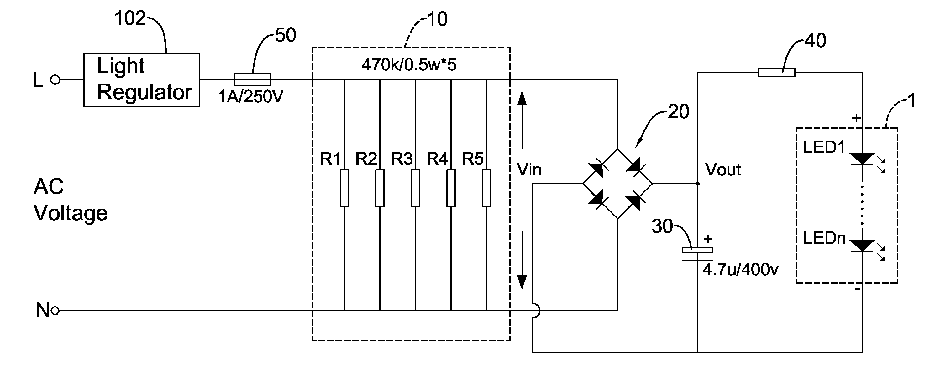
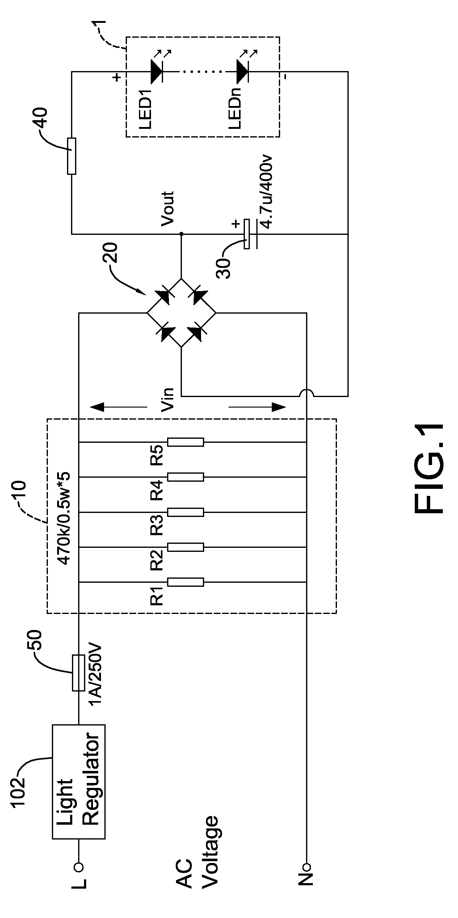
With reference to FIG. 1, a brightness adjusting circuit for an LED lamp (1) in accordance with the present invention is operated with a light regulator (102) and comprises a compensating circuit (10), a bridge rectifier (20), a filter capacitor (30) and a current limiting resistor (40) and may further have a fuse (50).

The light regulator (102) is connected to a first AC wire (L) and has an output terminal. The light regulator (102) comprises silicon-controlled elements such as a DIAC (diode for alternating current) and a TRIAC (triode for alternating current). The LED lamp (1) has a positive terminal and a negative terminal and comprises multiple LEDs connected in series.

The compensating circuit (10) is connected between the output terminal of the light regulator (102) and a second AC wire (N), and comprises multiple resistors (R1)˜(R5) connected in parallel. Preferably, all resistors (R1)˜(R5) have the same resistance value. A regulated input voltage (Vin) is established across th...


PUM


Abstract

A brightness adjusting circuit for an LED lamp has a compensating circuit, a bridge rectifier, a filter capacitor and a current limiting circuit. The compensating circuit is connected between an output terminal of a light regulator and an AC wire to output a regulated input voltage. The bridge rectifier is connected to the compensating circuit and converts the regulated input voltage to a DC voltage. The filter capacitor is connected to the bridge rectifier. The current limiting resistor is connected between the bridge rectifier and the LED lamp to limit a current flowing through the LED lamp. When the light regulator is adjusted, the regulated input voltage across is changed accordingly. Therefore, the DC voltage produced by the bridge rectifier is varied to regulate the brightness of the LED lamp.

Description

BACKGROUND OF THE INVENTION1. Field of the InventionThe present invention relates to a brightness adjusting circuit for a Light-emitting diode (LED) lamp, especially to a brightness adjusting circuit that allows a light regulator to control the brightness of the LED lamp.2. Description of the Related ArtLight adjustable lamps are often used to provide comfortable ambiance. With reference to FIG. 2, a conventional light adjustable lamp mainly includes an incandescent lamp (101) and a light regulator (102) connected in series. The light regulator (102) is composed of silicon-controlled elements such as DIAC (diode for alternating current) and TRIAC (triode for alternating current). By changing a trigging voltage applied to the silicon-controlled element, the conduction angle of the silicon-controlled element is adjusted to control the AC voltage across the incandescent lamp (101) and accordingly regulate the brightness of the incandescent lamp (101) to a desired level.More and more LE...

Claims


Application Information

Patent Timeline
IPC IPC(8): H05B37/02H05B44/00
CPCH05B33/0809Y02B20/348H05B33/0857H05B45/37Y02B20/30H05B45/10
Inventor LIN, CHIU-MIN
Owner LIN CHIU MIN
Why Eureka
Try Eureka