

Motor
- Summary
- Abstract
- Description
- Claims
- Application Information
AI Technical Summary
Benefits of technology
Problems solved by technology
Method used
Image

Examples
first embodiment
[0029]the present invention will now be described with reference to the drawings.
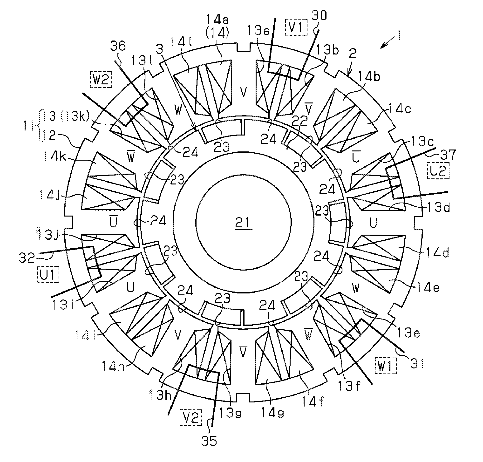
[0030]As shown in FIG. 1, an inner rotor type motor 1 according to the first embodiment includes an annular stator 2 and a rotor 3 arranged inside the stator 2.
[0031]The stator 2 has a stator core 11. The stator core 11 includes an annular portion 12 and twelve teeth 13 (first to twelfth teeth 13a to 13l), which extend radially inward from the annular portion 12. The teeth 13 are arranged at equal angular intervals in the circumferential direction. Coils 14 (14a to 14l) are wound around the teeth 13.
[0032]The rotor 3 includes a rotary shaft 21, a rotor core 22, seven magnets 23, and seven salient poles 24. The rotor core 22 is annular and formed by applying a magnetic metal material to the outer circumferential surface of the rotary shaft 21. The magnets are arranged at equal angular intervals in the circumferential direction of the rotor core 22 in a peripheral part of the rotor core 22. The salient po...
sixth embodiment
[0137]the present invention will now be described.
[0138]In the same manner as the rotors of the third to fifth embodiments, a rotor of the sixth embodiment is a consequent-pole rotor having an IPM structure in which permanent magnets are embedded in its rotor core.
[0139]The number of permanent magnets in the sixth embodiment is the same as the number of permanent magnets in the third to fifth embodiments, but the number of teeth of a stator of the sixth embodiment differs from the number of teeth of the stator in the third to fifth embodiments. Also, first to fourth permanent magnets M1 to M4 in the sixth embodiment are arranged at unequal angular intervals with its first to fourth angles θ12, θ23, θ34, and θ41 differing from the third to fifth embodiments.
[0140]Accordingly, items differing from the third to fifth embodiments will be described in detail, while items that are the same as the third to fifth embodiments will not be described for the sake of convenience.
[0141]FIG. 14 sc...
eighth embodiment
[0183]the present invention will now be described.
[0184]In the same manner as the rotors of the sixth and seventh embodiments, a rotor of the eighth embodiment is a consequent-pole rotor having an IPM structure in which permanent magnets are embedded in its rotor core. The number of stator teeth and the number of permanent magnets in the eighth embodiment are the same as those in the sixth and seventh embodiments. In the eighth embodiment, first to fourth permanent magnets M1 to M4 are arranged at unequal angular intervals with its first to fourth angles θ12, θ23, θ34, and θ41 differing from the sixth and seventh embodiments.
[0185]Accordingly, items differing from the sixth and seventh embodiments will be described in detail, while items that are the same as the sixth and seventh embodiments will not be described for the sake of convenience.
[0186]In a brushless motor 111 of the eighth embodiment, the first to fourth angles θ12, θ23, θ34, and θ41 differs from the motors of the sixth ...
PUM
 Abstract
Description
Claims
Application Information