Stopper structure for rotary operation member, electronic device, and channel stopper

a technology of electronic devices and stoppers, which is applied in the direction of electrical switches, resonance circuit tuning, electrical apparatus, etc., can solve the problems of difficult correct grasp by users, rotary operation members continue to be fumbled, and user often fumbles an operation, etc., to achieve sufficient axial-direction length, increase the number of parts, and the effect of sufficient radial-direction width

Active Publication Date: 2011-07-28
JVC KENWOOD CORP A CORP OF JAPAN
View PDF1 Cites 8 Cited by
  • Summary
  • Abstract
  • Description
  • Claims
  • Application Information

AI Technical Summary

Benefits of technology

[0018]This invention provides advantages explained below. A channel stopper is mounted on a rotational shaft, and fits in an axial hole of a rotary operation member. Thus, a sufficiently wide space can be formed between ends of the rotary operation member and the channel stopper and a member surface defining a bottom of an opening through which the rotational shaft extends. The space is used to accommodate an engagement projection provided on the chan

Problems solved by technology

The user often fumbles an operation part (for example, a rotary operation member) of the device on the belt when using the device.
Thus, in the case where an excessively large number of selectable radio channels is assigned to one rotary operation member, it tends to be difficult for the user to correctly grasp which of the channels is currently selected by actuating the rotary operation member.
Firstly, the rotary operation member continues to be fumbled and rotated in one direction until meeting a fixed stopper provided on a body of the device.
Secondly, the rotary operation member is fumbled and rotated reversely until the device tunes

Method used


Image

  • Stopper structure for rotary operation member, electronic device, and channel stopper
  • Stopper structure for rotary operation member, electronic device, and channel stopper
  • Stopper structure for rotary operation member, electronic device, and channel stopper

Examples


Embodiment Construction

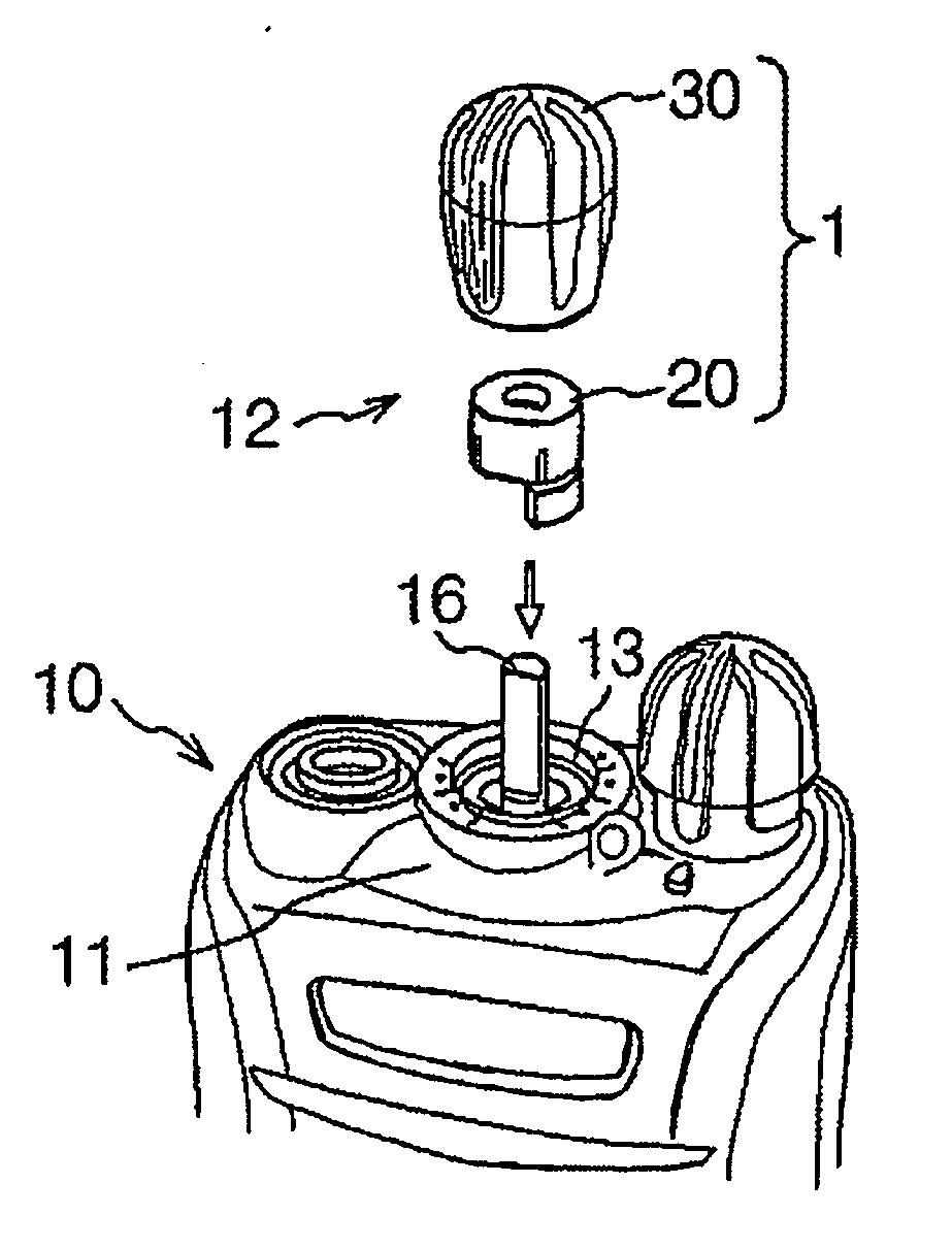
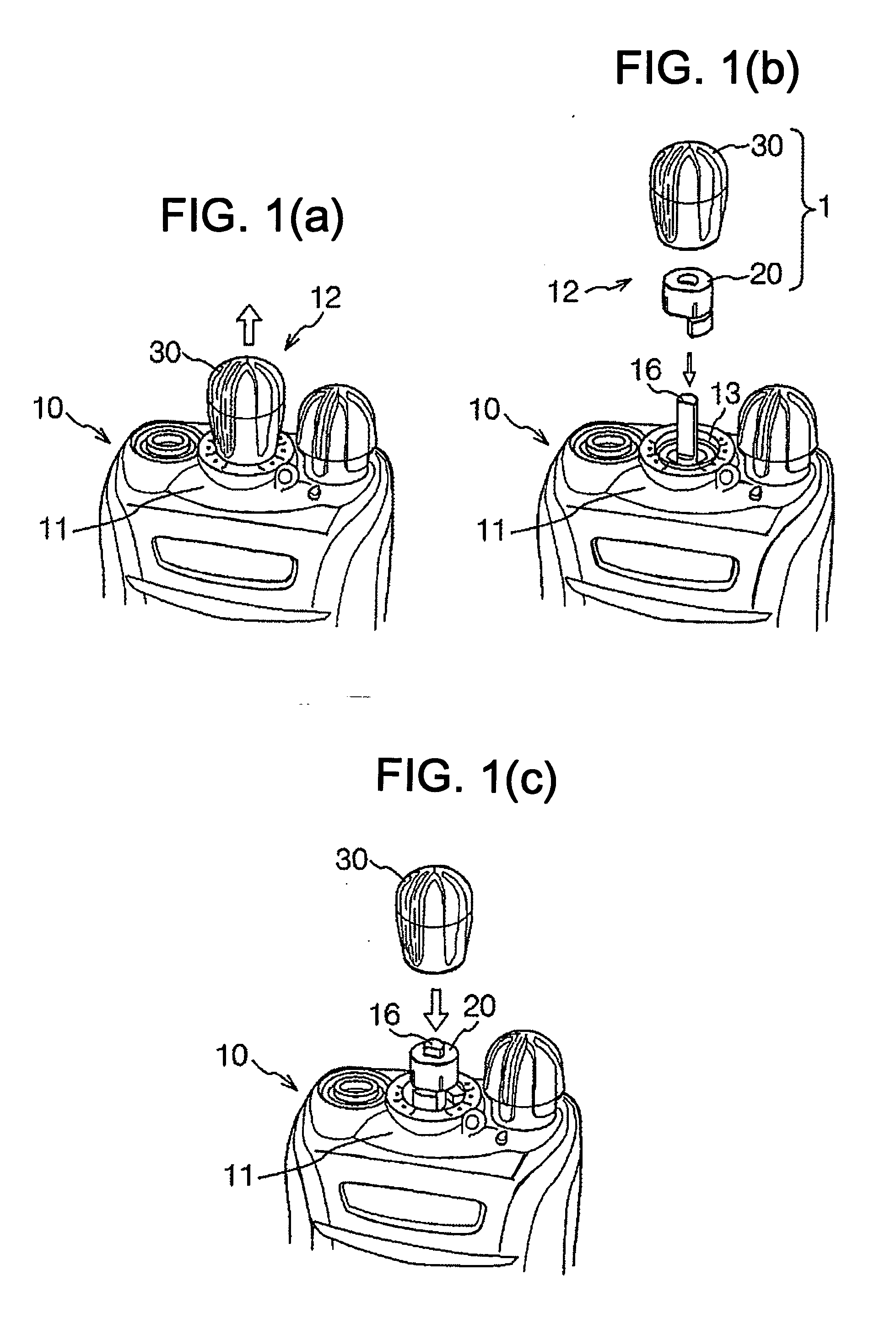
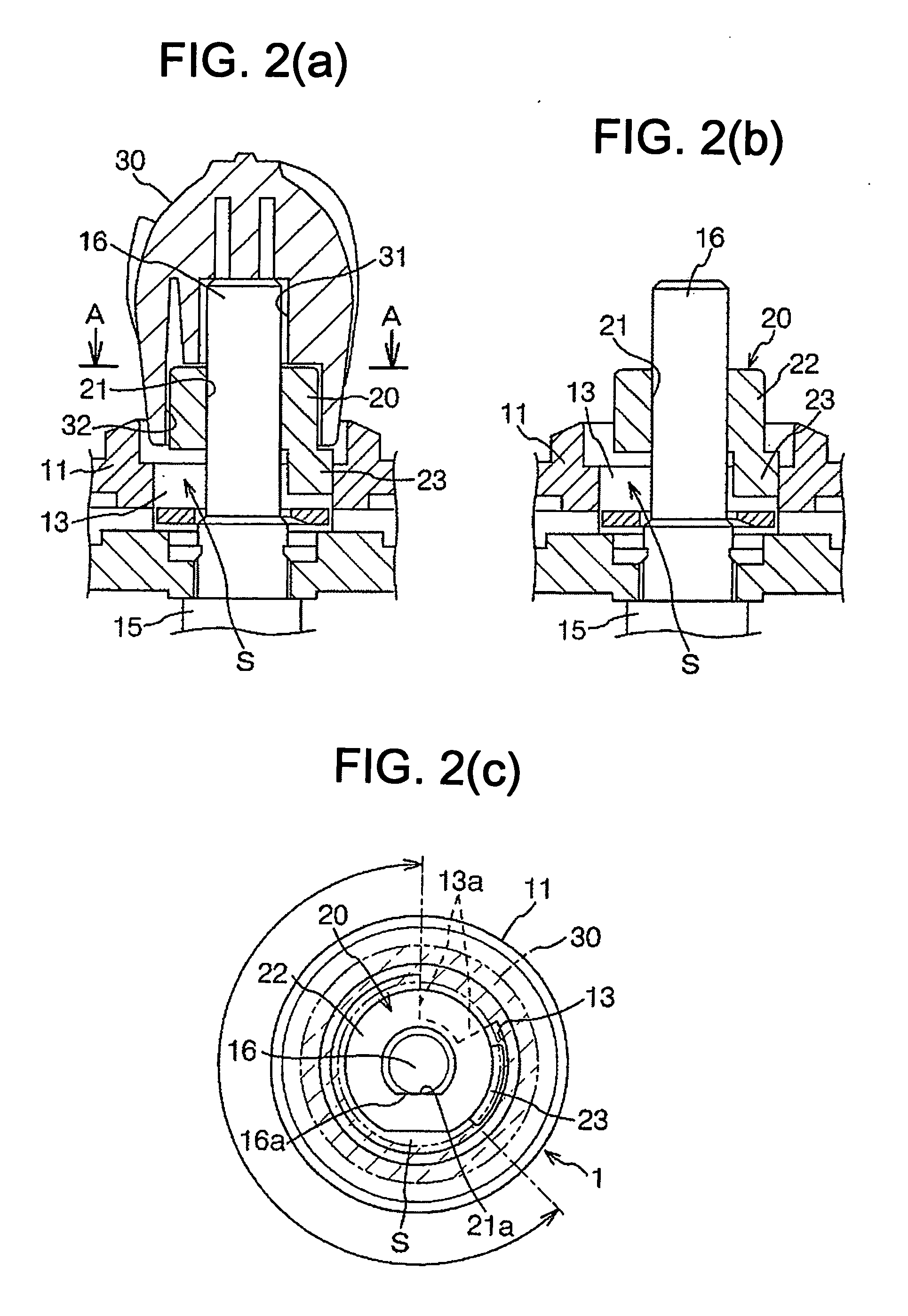
[0024]With reference to FIGS. 1(a)-1(c) and 2(a)-2(c), a portable radio communication device or an electronic device 10 has an operation part 12 provided with a stopper structure 1 in an embodiment of this invention. The stopper structure 1 is a means for limiting the range of rotation of a rotary operation member 30 accessible by a user and designed to operate a rotary encoder switch (a rotary electronic component) 15 in the radio communication device 10. The rotary encoder switch 15 is supported by the body or chassis of the radio communication device 10. The range of rotation of the rotary operation member 30 determines the number or range of radio channels usable by the radio communication device 10.

[0025]The rotary operation member 30 is included in the operation part 12 of the radio communication device 10, and is connected with the rotary encoder switch 15. The stopper structure 1 is designed to allow easy implementation of change in the range of rotation of the rotary operat...


PUM


Abstract

A stopper structure includes a wall defining an opening. A rotary electronic component has a rotational shaft extending through the opening. A channel stopper has a tubular body and an engagement projection. The tubular body is detachably mounted on the rotational shaft and is inhibited from rotating relative thereto. The engagement projection extends from an end of the tubular body in an axial direction and a radial direction with respect to the rotational shaft. A rotary operation member is detachably mounted on the rotational shaft and the tubular body and is inhibited from rotating relative thereto. The rotary operation member has an axial hole in which at least portions of the rotational shaft and the tubular body fit. A limiting portion provided on the wall is engageable with the engagement projection for liming a range of rotation of the rotational shaft.

Description

BACKGROUND OF THE INVENTION[0001]1. Field of the Invention[0002]This invention relates to a stopper structure for limiting the range of rotation of a rotary operation member designed to operate, for example, a rotary encoder switch provided in a radio communication device and used to change a used radio channel. This invention further relates to an electronic device and a channel stopper.[0003]2. Description of the Related Art[0004]Some business-use radio communication devices or portable radio communication devices have rotary encoder switches for changing used radio channels. The rotary encoder switches each have a rotational shaft. As the rotational shaft is rotated, the used radio channel is changed.[0005]It is known to mount a rotary operation member accessible by a user on the rotational shaft of a rotary encoder switch. As the rotary operation member is rotated by the user, the encoder shaft rotates accordingly so that the used radio channel is changed. Thus, the user can tun...

Claims


Application Information

Patent Timeline
IPC IPC(8): H03J1/00
CPCH01H19/03
Inventor YAMADA, TADAHIROOTA, SHOJI
Owner JVC KENWOOD CORP A CORP OF JAPAN
Why Eureka
Try Eureka