Image processing device and image processing method

a technology of image processing and image quality, applied in the field of image encoding devices, can solve the problems of inability to obtain uniform image quality as a whole, inability to achieve uniform image quality, and inability to achieve image quality degradation, etc., and achieve the effect of reducing the circuit scal

Inactive Publication Date: 2011-07-28
SONY CORP
View PDF42 Cites 17 Cited by
  • Summary
  • Abstract
  • Description
  • Claims
  • Application Information

AI Technical Summary

Benefits of technology

[0014]Accordingly, the image processing device does not need to store encoding values of one line of an encoding block at the lower end in a scan block.
[0017]Accordingly, the image processing method does not need to store encoding values of one line of an encoding block at the lower end in a scan block.

Problems solved by technology

Therefore, in the image encoding device according to such a related art, the quantization step increases to degrade image quality when complicated images continue, whereas the quantization step decreases when simple images continue, so that uniform image quality cannot be obtained as a whole.
However, in the above-described method of step 2 of TM5, degradation of image quality may occur in encoding of picture at the top of a sequence or a picture just after change of a scene because the initial value of the quantization step does not conform to the pattern of the picture.
Also, in the image encoding device, the target code quantity of an MB is always kept constant, and thus inappropriate distribution of code quantity occurs when difficulty of an image is uneven in a screen.
However, the hardware scale thereof is large, and it is desired to reduce the circuit scale.

Method used


Image

  • Image processing device and image processing method
  • Image processing device and image processing method
  • Image processing device and image processing method

Examples


first embodiment

1. First Embodiment

[0036][1-1. Configuration of Image Encoding Device]

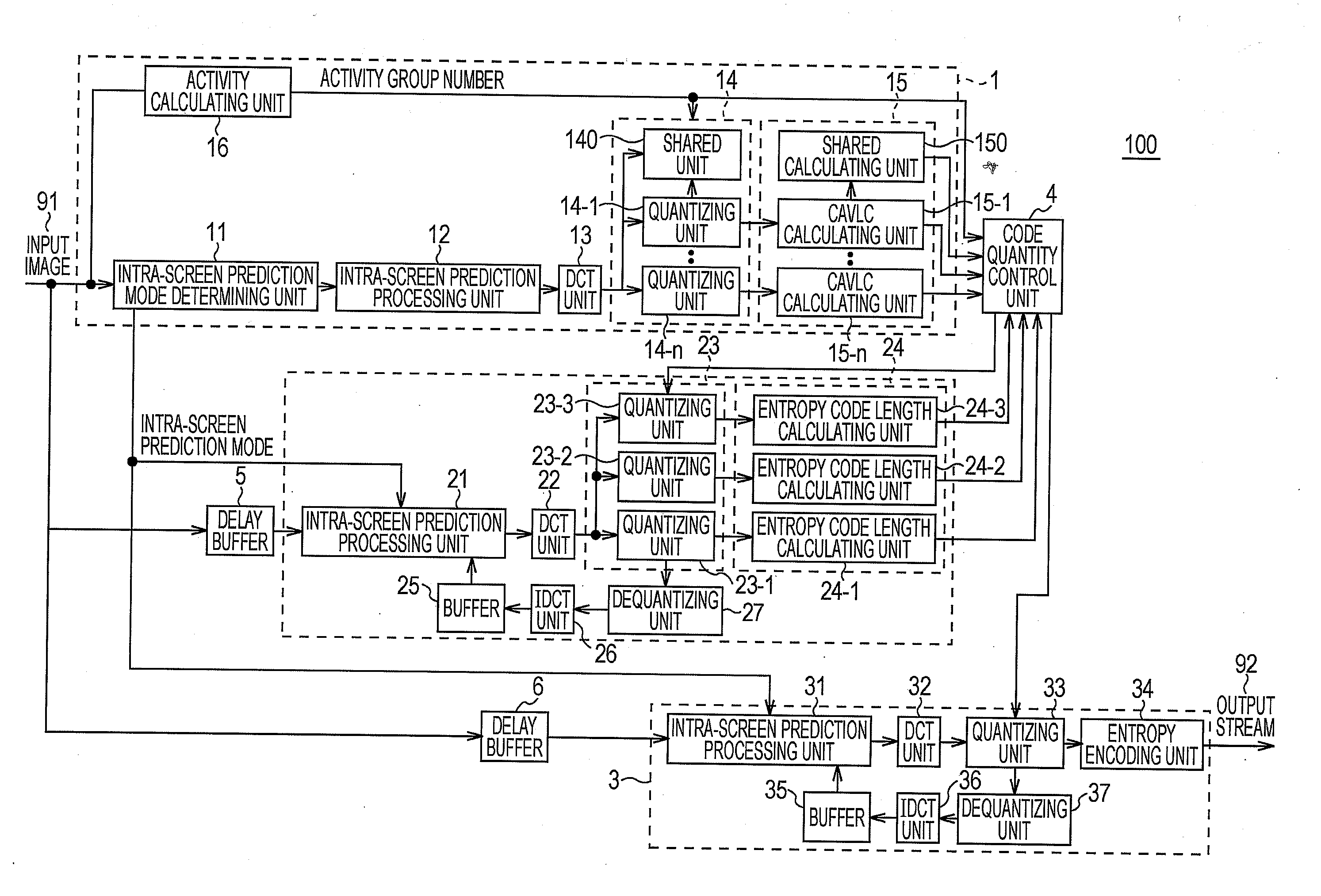
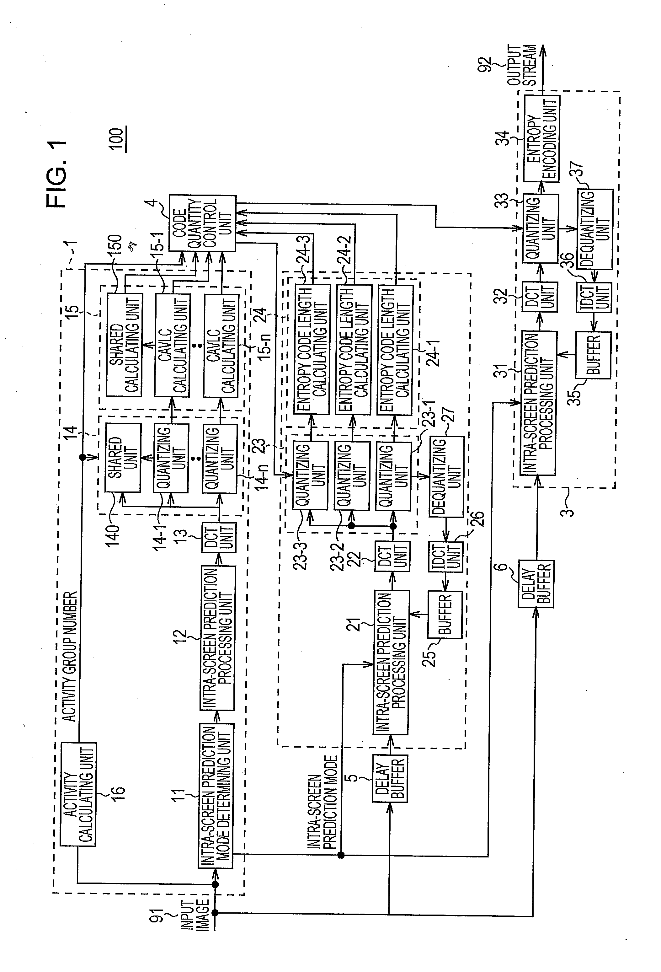
[0037]FIG. 1 illustrates and describes a configuration of an image encoding device 100 according to an embodiment of the present invention.

[0038]The image encoding device 100 includes a first pre-encoding unit 1, a second pre-encoding unit 2, a main encoding unit 3, a code quantity control unit 4, and delay buffers 5 and 6.

[0039]In order to perform code quantity control, the image encoding device 100 performs pre-encoding in advance using the first pre-encoding unit 1 and the second pre-encoding unit 2, thereby determining main encoding information used in the main encoding unit 3, such as a basic quantization parameter QPMB, a predictive quantization matrix Q MatrixD, an intra-screen prediction mode, and an activity group.

[0040]At this time, the first pre-encoding unit 1 performs parallel pre-encoding using a wide range of quantization parameters QP, with the precision being slightly decreased and the circuit sca...

second embodiment

2. Second Embodiment

[0150]A second embodiment illustrated in FIGS. 6 to 13 is different from the first embodiment in that a preceding mode estimation pre-encoding unit 40 is provided.

[0151][2-1. Back Search]

[0152]The present invention relates to, for example, an image encoding device or the like, and specifically relates to a technical field of preventing degradation during dubbing and performing control to obtain a desired main encoding generated code quantity during main encoding.

[0153]Conventionally, when video data is transmitted between television broadcast stations or when copying of video data is performed using a plurality of video tape recorders (VTR devices), an encoder and a decoder need to be connected tandem in series because video data that is compressed and encoded using an MPEG (Moving Picture Experts Group) 2 method is decompressed and decoded, and is compressed and encoded again.

[0154]Then, a method that is so-called “back search” is employed as a method for reduci...


PUM


Abstract

The present invention enables a circuit configuration to be simplified. An image encoding device (100) receives an input image (91) that is line-scanned in units of MBs as scan blocks, each constituted by a plurality of 4×4 blocks, while being scanned in units of 4×4 blocks as encoding blocks, each constituted by a plurality of pixels. The image encoding device (100) selects a VLC (variable length) table corresponding to a table selection index nC, which is an average value of the numbers nB and nA of nonzero coefficients as encoding values on which variable-length encoding is performed in upper-adjoining and left-adjoining 4×4 blocks of a 4×4 block as an encoding target in quantization coefficients as encoding target data based on the input image (91). At this time, in a case where the 4×4 block as an encoding target is at an upper end of an MB, the image encoding device (100) equates the number nB of nonzero coefficients of the upper-adjoining 4×4 block with the number nA of nonzero coefficients of the left-adjoining 4×4 block. The image encoding device (100) performs variable-length encoding on the number of nonzero coefficients of a 4×4 block as an encoding target in quantization coefficients using the selected VLC table.

Description

TECHNICAL FIELD[0001]The present invention relates to, for example, an image encoding device or the like, and specifically relates to a technical field of adjusting a generated code quantity to a target code quantity given to one picture without executing intra-screen feedback control.BACKGROUND ART[0002]Conventionally, in a system or the like for transmitting a bit stream of moving images or recording the bit stream on a recording medium, high-efficiency encoding is performed to efficiently use a transmission path or recording capacity. In an image encoding device for realizing the high-efficiency encoding, the encoding bit rate of a bit stream generated by an encoder is set to a certain rate according to the transfer rate of a transmission medium. Under this restriction, the quantity of data to be generated, i.e., the quantization step of quantization in the encoder, is controlled. That is, the image encoding device increases the quantization step to suppress the quantity of data ...

Claims


Application Information

Patent Timeline
Patent Type & Authority Applications(United States)
IPC IPC(8): G06K9/00
CPCH04N19/176H04N19/146H04N19/13H04N19/196
Inventor SHIBATA, SHOJIROFUCHIE, YAKAAKITAKAHASHI, KASHUHORIUCHI, YUYA
Owner SONY CORP
Why Eureka
Try Eureka