Dental implant adaptor

a technology for dental implants and adapters, applied in dental surgery, medical science, impression caps, etc., can solve the problems of difficult crown retrieval, unsatisfactory optical scanning shape of current implant/abutment components, and inability to universally popularize protocol

Inactive Publication Date: 2011-07-28
SOUTHERN IMPLATS (PTY) LTD
View PDF22 Cites 15 Cited by
  • Summary
  • Abstract
  • Description
  • Claims
  • Application Information

AI Technical Summary

Benefits of technology

[0018]a scanning and locating insert made of plastics material and having a tapered distal end and a threaded proximal end, the insert being shaped for its proximal end to be screwed int...

Problems solved by technology

The shapes of the current implant/abutment components are however not ideal for optical scanning in situations where a “screw retained” protocol, in which the crown is held in position by a screw, is used.
Where a “closed crown cemented” protocol is used, the relevant components are more suited to optical scanning but the ...

Method used


Image

  • Dental implant adaptor
  • Dental implant adaptor
  • Dental implant adaptor

Examples


Embodiment Construction

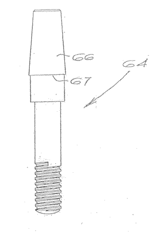
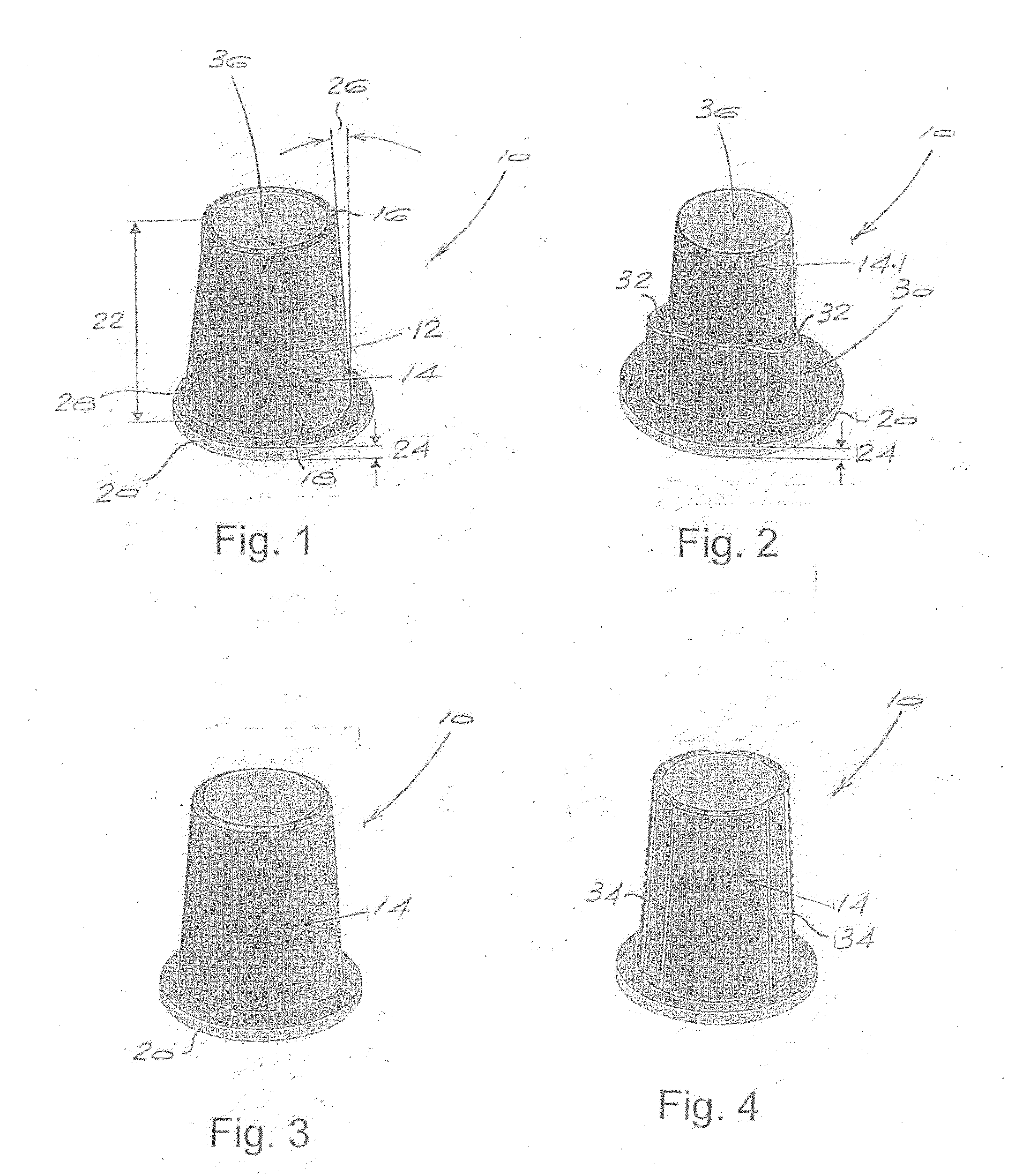
[0064]FIG. 1 shows a first embodiment of dental implant adaptor 10 according to the invention. The view in this Figure is taken from the coronal end of the adaptor.

[0065]The adaptor 10 is made of a suitable non-corrosive and bio-compatible material, typically a suitable grade of titanium. The adaptor 10 includes a hollow body 12 including a generally conically tapered, crown-receiving or abutment portion 14 extending from a relatively narrow, distal or coronal end 16 to a relatively wide, opposite, proximal end 18. The hollow body 12 also includes a collar 20 which projects laterally at the relatively wide, proximal end. In general it is preferred that the overall axial length of the crown-receiving portion and collar together is in the range 3.5 mm to 7 mm, preferably 4 mm to 6 mm. The axial thickness of the collar is preferably 1.5 mm or less, most preferably in the range 0.2 mm to 0.7 mm. In this example the collar has an axial thickness of the order of 0.3 mm and the crown-recei...


PUM


Abstract

A dental implant adaptor which is particularly suitable for dental crown implantation using a screw-retained protocol has a hollow body that can be mounted on a dental implant. The body includes a crown-receiving portion on which a dental crown can be mounted. The portion has a distal end and a proximal end and includes a first anti-rotation formation to prevent rotation between the adaptor and the crown. The body also has a laterally projecting collar at the proximal end of the crown-receiving portion which, in use, locates on the implant. There is also a second anti-rotation formation shaped for non-rotational engagement with the implant. The crown-receiving portion and collar together have an overall axial length in the range 3.5 mm to 7 mm and the collar has an axial thickness of 1.5 mm or less. Another described is an implant assembly incorporating the adaptor.

Description

BACKGROUND TO THE INVENTION[0001]THIS invention relates to a dental implant adaptor.[0002]A conventional dental implant assembly consists of an implant, an abutment and a crown. The implant has a threaded shank which is screwed into the bone, the abutment is then fastened to the implant and the crown, which has the appearance of the original tooth and which is visible in the mouth after implantation, is fastened to the abutment.[0003]While the implant and abutment may have standard designs, the crown must be individually manufactured in a dental laboratory. In modern practice a digital camera is placed in the patient's mouth or over a model thereof and optical scanning is used to register the position and shape of the implant and abutment, and the corresponding part of the crown is shaped according to the scanned data.[0004]The shapes of the current implant / abutment components are however not ideal for optical scanning in situations where a “screw retained” protocol, in which the cr...

Claims


Application Information

Patent Timeline
IPC IPC(8): A61C8/00
CPCA61C8/0001A61C8/005A61C8/006A61C2008/0084A61C8/0068A61C9/0053A61C8/0066
Inventor GALGUT, DANAGELDENHUYS, GIUSEPPEBLACKBEARD, GRAHAM ALAN
Owner SOUTHERN IMPLATS (PTY) LTD
Why Eureka
Try Eureka