Healing cap for dental implants

a technology for dental implants and caps, applied in the field of dental implants, can solve the problems of reduced head protection, no improvement in vestibular region, and caps are generally not suitable, and achieve the effect of improving handling

Inactive Publication Date: 2000-09-19
STRAUMANN HLDG AG
View PDF11 Cites 100 Cited by
  • Summary
  • Abstract
  • Description
  • Claims
  • Application Information

AI Technical Summary

Benefits of technology

For the period after the healing phase, that is to say between the impression-taking and the fabrication of the crown, a protective cap which can be fixed on the implant and rests on the shoulder of the implant is proposed for the purpose of replacing the healing cap. This protective cap is cylindrical and can be ground as desired, or it is bevelled and anatomically preformed such that the rough contour of a tooth is at least approximately produced. The protective cap is used as a simple temporary provision for closing the gap between the teeth and for protecting the emergent profile of the gingiva, the shoulder of the implant and the inserted secondary part.
The invention now provides a healing cap by means of which the gingiva is shaped into a position which appears natural, i.e. the surrounding soft parts are aesthetically conditioned. Furthermore, the healing cap ensures a firm seating which is as far as possible free of gaps on the implant, and significantly improved handling is provided. When using an occlusal screw, the latter is screwed into the healing cap before the latter is inserted, so that in principle only one part has to be handled. The unthreaded shank part on the occlusal screw allows the latter to be screwed tight freely, without concomitant rotation of the protective cap, since, when the occlusal screw is turned in relatively deeply, the external thread of the screw shank becomes disengaged from the internal thread situated in the healing cap.

Problems solved by technology

The healing caps mentioned to this extent have the drawback that, due to their contour, they do not contribute optimally to preforming the gingiva, and are felt by the patient to be intrusive, particularly in the anterior and posterior regions; the healing caps with a reduced head no longer protect the shoulder of the implant.
Although these healing caps may sometimes have a positive effect on the preforming of the gingiva, no improvement is achieved in the vestibular region.
In addition, these healing caps are generally not suitable for implants with a bevelled shoulder.
In addition to the abovementioned disadvantages, these healing caps are extremely tricky to handle, in view of the two small parts--the healing cap and the occlusal screw put in separately.

Method used


Image

  • Healing cap for dental implants
  • Healing cap for dental implants
  • Healing cap for dental implants

Examples


Embodiment Construction

FIGS. 1A and 1B

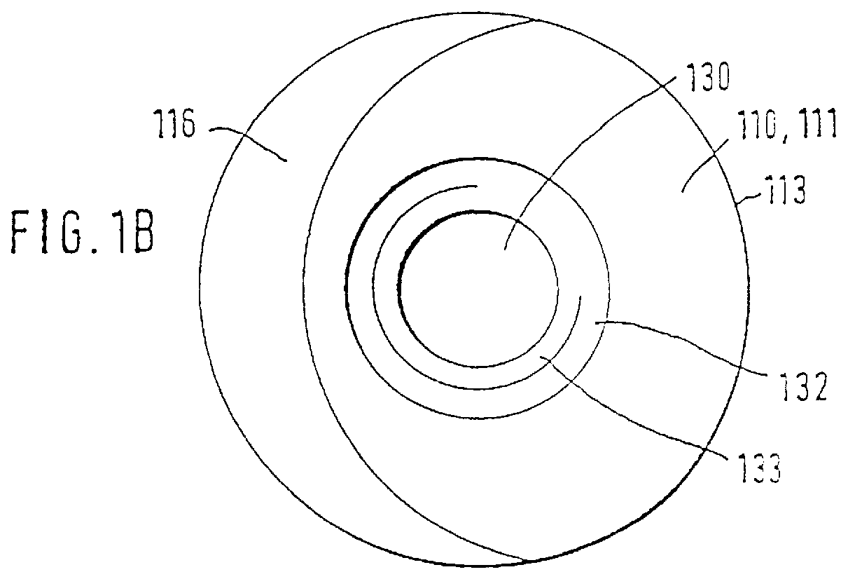
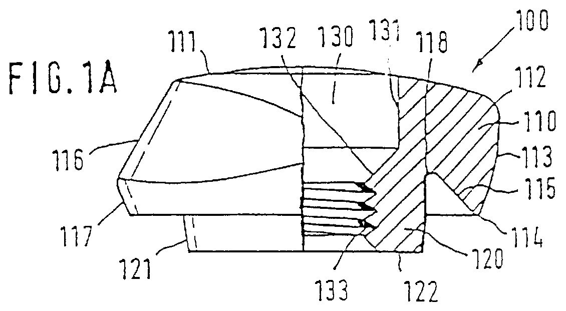
At the top, the healing cap 100 has a roof part 110 which in principle is cylindrical and mushroom-shaped and a pin 120 which begins centrally on the underside of the roof part 110. A through-bore 130 extends axially through the healing cap 100.

The top surface 111 of the roof part 110 is slightly convex and the transition 112 to the outer, circumferential surface 113 is rounded off. The circumferential surface 113 is likewise convex and leads into the circular shoulder edge 114. From the shoulder edge 114 towards the pin 120, there exists a conical surface in the form of a circular ring, which forms the complementary mating shoulder 115 for the shoulder 10 of the implant (cf. FIGS. 3A and 3B). In the labially positioned region, a bevel 116, which starts at the top surface 111, is provided on the circumferential surface 113. The bevel 116 extends over approximately half the circumferential surface 113, tapers smoothly downwards and ends before reaching the shoulder edg...


PUM


Abstract

PCT No. PCT/CH96/00426 Sec. 371 Date May 27, 1998 Sec. 102(e) Date May 27, 1998 PCT Filed Dec. 3, 1996 PCT Pub. No. WO97/20518 PCT Pub. Date Jun. 12, 1997A healing cap (100) is distinguished by a bevel (116), particularly in the region to be positioned labially, the bevel being advantageous for conditioning the soft parts, as well as a firm bearing on the associated implant (1), which is achieved by means of a mating shoulder (115) and an adaptable end portion (121) of a pin (120) or a centering bead. An occlusally applicable screw (200) can be mounted in the healing cap (100) beforehand, making it easier to handle. A special protective cap is provided as an intermediate treatment and as a temporary sealing element.

Description

APPLICATION AREA OF THE INVENTIONThe invention relates to a healing cap which can be fixed on an intraossally positioned dental implant and has a mating shoulder which can be matched to the shoulder of the implant and which lies below the roof part of the healing cap. Furthermore, the invention comprises an occlusally applicable screw for fixing the healing cap on the implant, as well as a protective cap as a temporary provision following removal of the healing cap for sealing and protecting the implant.When inserting an implant into the maxilla or the mandibula, the surgical procedure of intra-ossal implantation in principle ends with the positioning of a special healing cap, before the papillae and the gingiva are repositioned as precisely as possible and are adapted using sutures. These healing caps, which generally consist of a biocompatible material, extend the implant, during the healing phase, which lasts a number of months, as far as the surface of the soft tissue. This thus...

Claims


Application Information

Patent Timeline
Patent Type & Authority Patents(United States)
IPC IPC(8): A61C8/00
CPCA61C8/008
Inventor BUSER, DANIELSCHAR, ALEX
Owner STRAUMANN HLDG AG
Why Eureka
Try Eureka