Electronic Torque Wrench

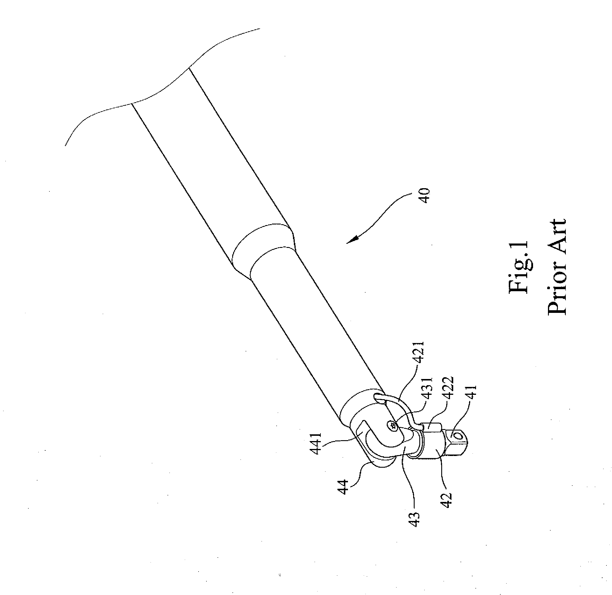
a technology of electronic torque wrench and torque wrench, which is applied in the direction of wrenches, screwdrivers, manufacturing tools, etc., can solve the problems of increasing the length of the drive member, the inability of electronic torque wrenches to provide precise torque detection, and the limitation of the use of electronic torque wrenches b>40, so as to facilitate the description of the invention

Inactive Publication Date: 2011-08-04
HU BOBBY
View PDF5 Cites 15 Cited by
  • Summary
  • Abstract
  • Description
  • Claims
  • Application Information

AI Technical Summary

Benefits of technology

[0026]All figures are drawn for ease of explanation of the basic teachings of the present invention only; the extensions of the figures with respect to number, position, relationship, and dimensions of the parts to form the preferred embodiments will be explained or will be within the skill of the art after the following teachings of the present invention have been read and understood. Further, the exact dimensions and dimensional proportions to conform to specific force, weight, strength, and similar requirements will likewise be within the skill of the art after the following teachings of the present invention have been read and understood.
[0027]Where used in the various figures of the drawings, the same numerals designate the same or similar parts. Furthermore, when the terms “first”, “second”, “third”, “fourth”, “outer”, “end”, “portion”, “section”, “longitudinal”, and similar terms are used herein, it should be understood that these terms have reference only to the structure shown in the drawings as it would appear to a person viewing the drawings and are utilized only to facilitate describing the invention.

Problems solved by technology

However, these electronic torque wrenches could not provide precise detection of torque if the rotating axis of the driving portion of the electronic torque wrench is at an acute angle to the longitudinal axis of the object, as mentioned above.
However, mounting the torque sensor 42 on the drive member 43 requires an increase in the length of the drive member 43, leading to limitation to use of electronic torque wrench 40 in a limited space.
Furthermore, torque sensor 42 mounted to the outer periphery of the intermediate portion of drive member 43 is liable to be impinged and, thus, damaged.

Method used


Image

  • Electronic Torque Wrench
  • Electronic Torque Wrench
  • Electronic Torque Wrench

Examples


first embodiment

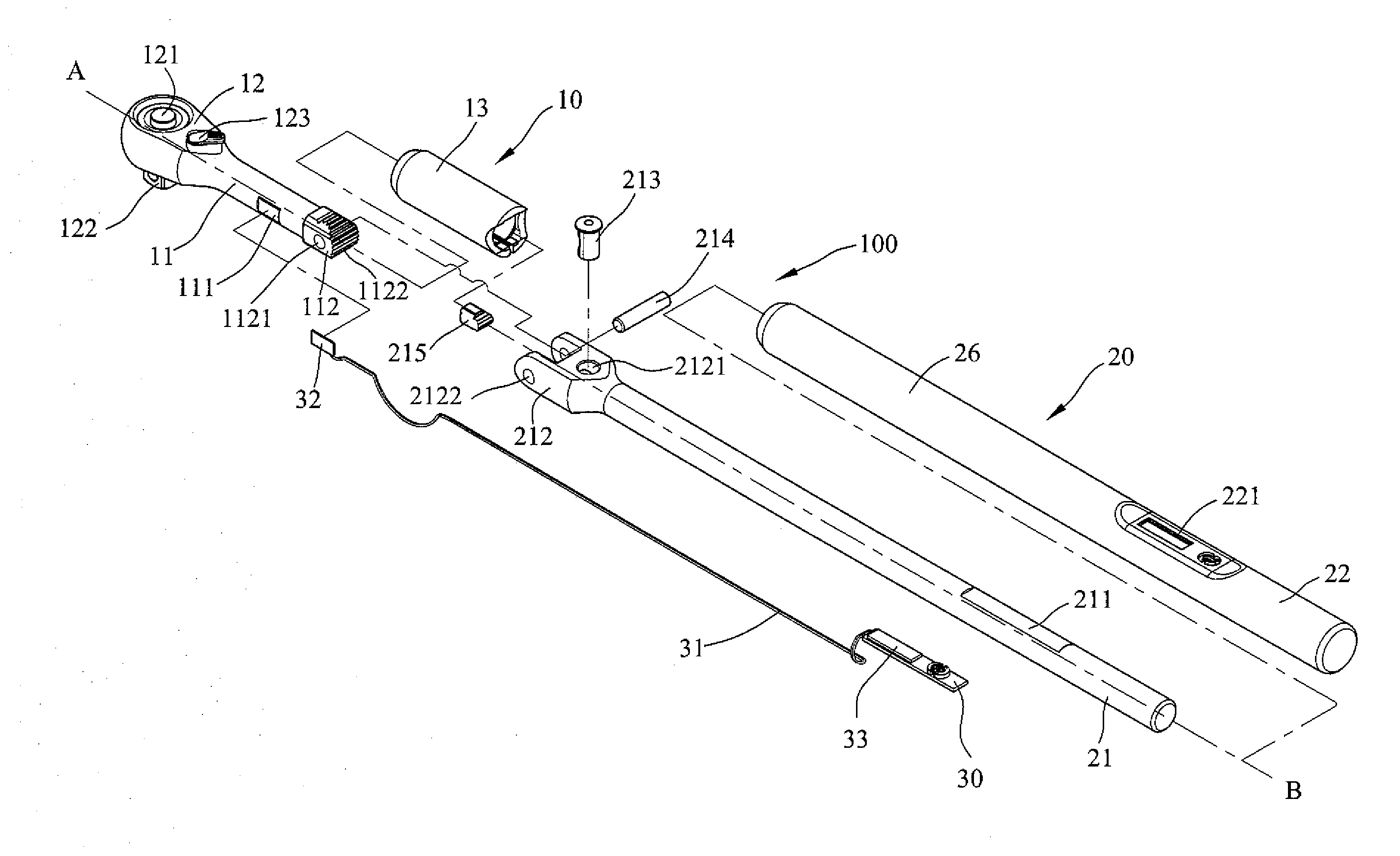
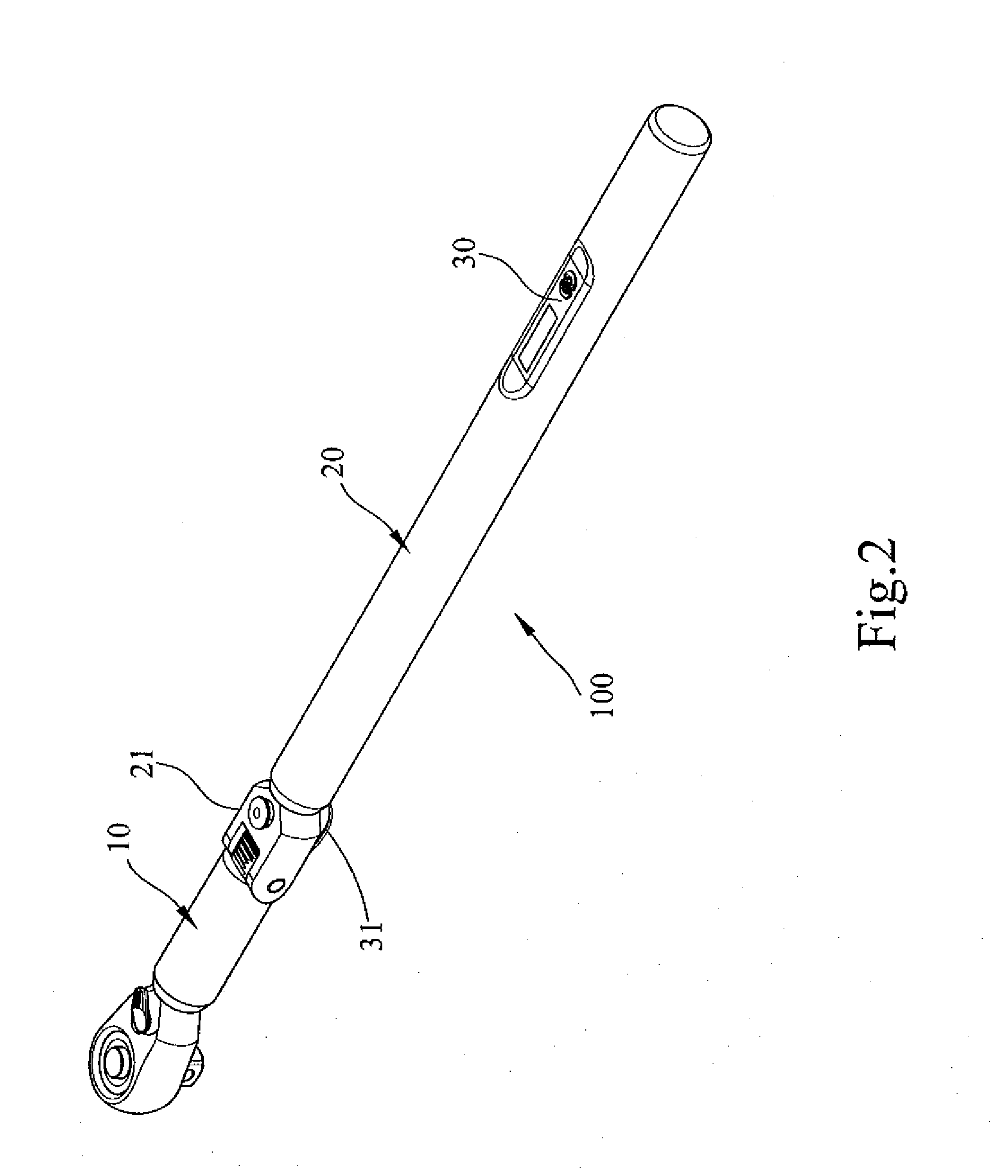
[0028]An electronic torque wrench according to the preferred teachings of the present invention is shown in FIGS. 2-11 and generally designated 100. shown in FIGS. 2-5, electronic torque wrench 100 includes a body 10, a handle 20, and a torque display device 30. Body 10 includes a driving portion 12 and a shank 11 interconnected to driving portion 12. Driving portion 12 is adapted to directly or indirectly drive an object such as a fastener in the form of a bolt, nut, etc. Driving portion 12 includes a drive column 122 for releasably engaging with a socket. Driving portion 12 is of the type having a ratcheting portion 121 and a switch 123 allowing switching of a driving direction in which the object is driven. However, other types and forms of driving portion 12 can be utilized according to the teachings of the present invention.

[0029]Shank 11 includes a pivotal portion 112 spaced from driving portion 12 along a longitudinal axis A. In this embodiment, pivotal portion 112 includes ...

second embodiment

[0033]FIGS. 6-8 show electronic torque wrench 100 of a second embodiment according to the preferred teachings of the present invention. Specifically, pivotal portion 112 is disengaged from pivotal portion 212, and, an extension 23 is mounted between pivotal portions 112 and 212. Extension 23 includes two pivotal portions 231 and 232 spaced along longitudinal axis A. Pivotal portion 231 is pivotably and releasably engaged with pivotal portion 112, and pivotal portion 232 is pivotably and releasably engaged with pivotal portion 212. In the illustrated embodiment, pivotal portion 232 includes two spaced lugs defining a groove and having aligned pin holes 2322. Pivotal portion 112 is received in the groove between the spaced lugs of pivotal portion 232, and a pin 234 is extended through pin holes 2322 and pivotal hole 1121, allowing relative pivotal movement between pivotal portions 112 and 232. Pivotal portion 232 further includes a hole 2321 receiving a release pin 233. A catch 235 is...


PUM


Abstract

An electronic torque wrench includes a body (10) having a driving portion (12; 15; 16; 17) and a shank (11) interconnected to the driving portion (12; 15; 16; 17). The shank (11) includes a first pivotal portion (112) spaced from the driving portion (12; 15; 16; 17) along a longitudinal axis (A). An object can be driven by the driving portion (12; 15; 16; 17) to rotate about a rotating axis perpendicular to the longitudinal axis (A). A torque sensor (32) is mounted to a detecting portion (111) of the shank (11) intermediate the first pivotal portion (112) and the driving portion (12; 15; 16; 17). A handle (20) includes a second pivotal portion (212) pivotably connected to the first pivotal portion (112). A torque display device (30) is mounted to the handle (20) and electrically connected to the torque sensor (32). The torque sensor (32) detects torque applied from the driving portion (12; 15; 16; 17) to the object and sends a signal indicative of the torque to the torque display device (30). The torque display device (30) receives the signal and displays a value of the torque.

Description

BACKGROUND OF THE INVENTION[0001]The present invention relates to an electronic torque wrench and, more particularly, to an angle-adjustable electronic torque wrench allowing precise detection of torque.[0002]Currently available electronic torque wrenches include a handle having a driving portion on an end thereof and a gripping portion on the other end thereof. The driving portion can include a ratchet wheel, a closed end, or an open end. At lease one torque sensor is mounted to an outer periphery of the handle to detect the bending strain of the handle when the electronic torque wrench is applying a force to an object such as a fastener. The torque sensor coverts a change in the strain into a signal that is sent via a wire to a torque display device mounted to the handle. The torque display device includes a torque calculating device that receives the signal and converts the signal into a torque value that is displayed on a display of the torque display device. Thus, the user can ...

Claims


Application Information

Patent Timeline
Patent Type & Authority Applications(United States)
IPC IPC(8): B25B23/14
CPCB25G1/066B25B23/1425
Inventor HU, BOBBY
Owner HU BOBBY
Why Eureka
Try Eureka