Retrofit Clamp for MUX, Umbilicals and IWOCS

a technology of umbilical cords and retrofit clamps, which is applied in the direction of kitchen equipment, domestic applications, and stands/trestles. it can solve the problems of inoperable components, communication lines that are not properly coupled to subsea components, and various components are at risk of being damaged

Active Publication Date: 2011-08-04
THE SUBSEA
View PDF5 Cites 20 Cited by
  • Summary
  • Abstract
  • Description
  • Claims
  • Application Information

AI Technical Summary

Problems solved by technology

Currently mechanisms which bind various well control lines to drill strings fall short of effectively coupling components which are used in drilling and production of oil, gas, and other minerals.
Unfortunately, communication lines inadequately couple to components which are run subsea.
When communication lines are inadequately coupled to the riser string, the various components are at risk of being damaged and are rendered inoperable.
In conventional installations, the failure of a riser or its release from the subsea installation due to tripping of a blowout preventer cuts these various lines as they are integrated in the riser.
Presently numerous coupling mechanisms fail to appropriately couple communication lines and allow for interference from physical damage, and sometimes even sea life in subsea applications.
When a riser and various pipes are lowered and raised from drilling and / or work-over rigs a coupling mechanism is mounted to riser joints at inappropriate locations which causes extra pauses during the runs to attached said lines and therefore increasing the deployment times dramatically.
This is somewhat problematic, due to rig day-rate costs and auxiliary services employed in drilling and servicing oil wells.
In some cases “cutouts” or cavities are provided in the floatation to allow for the mounting of the control cable clamps at an appropriate location so that the cables / hoses can be attached in conjunction with the addition of the next joint of riser, but this is not always the case.
Where the floatation is not supplied with this feature the clamps have to be fitted either above or below the floatation which adds an extra stopping point for each joint during the run, thus adding an inordinate amount of time to the riser run.

Method used


Image

  • Retrofit Clamp for MUX, Umbilicals and IWOCS
  • Retrofit Clamp for MUX, Umbilicals and IWOCS
  • Retrofit Clamp for MUX, Umbilicals and IWOCS

Examples


Embodiment Construction

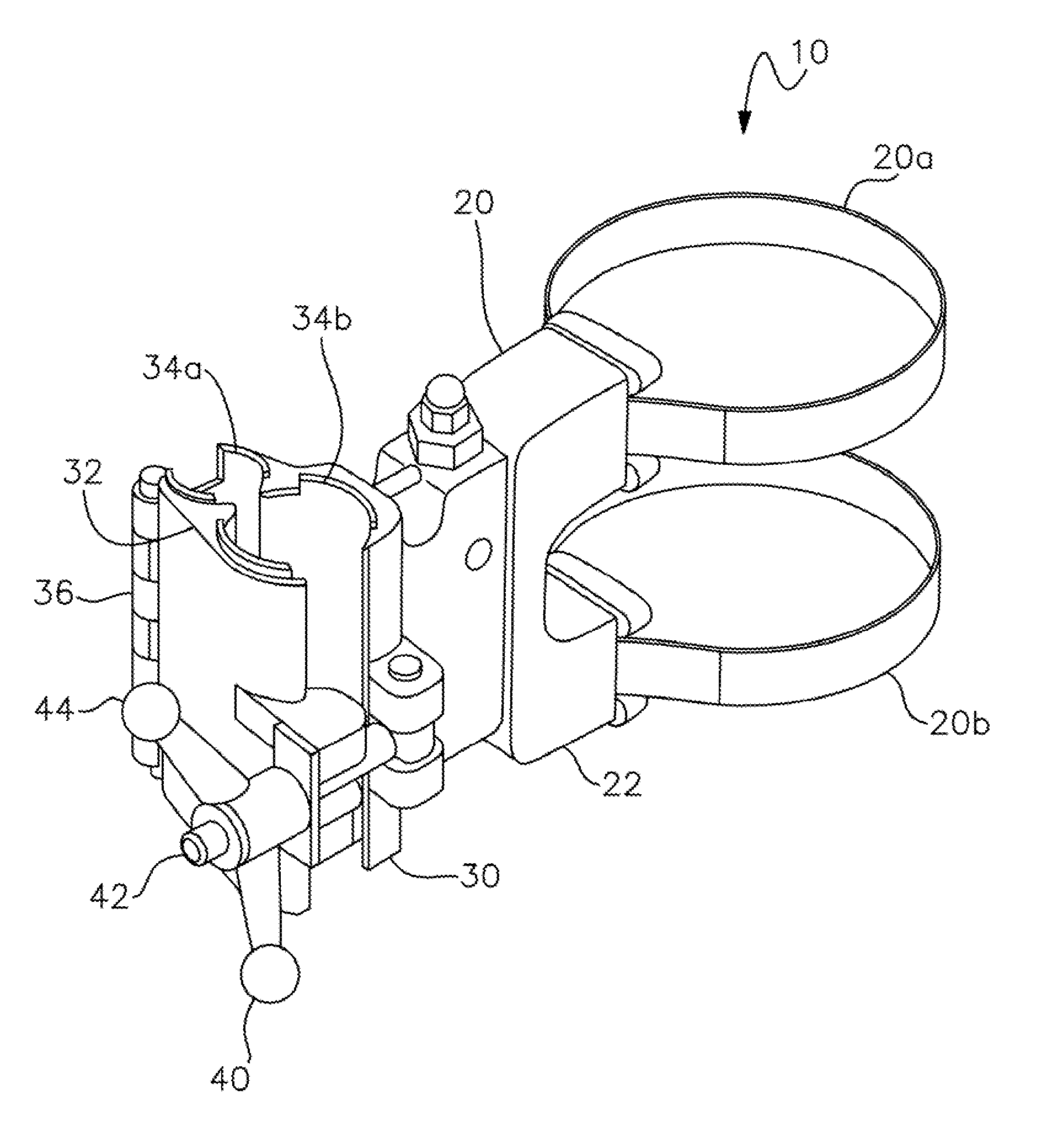
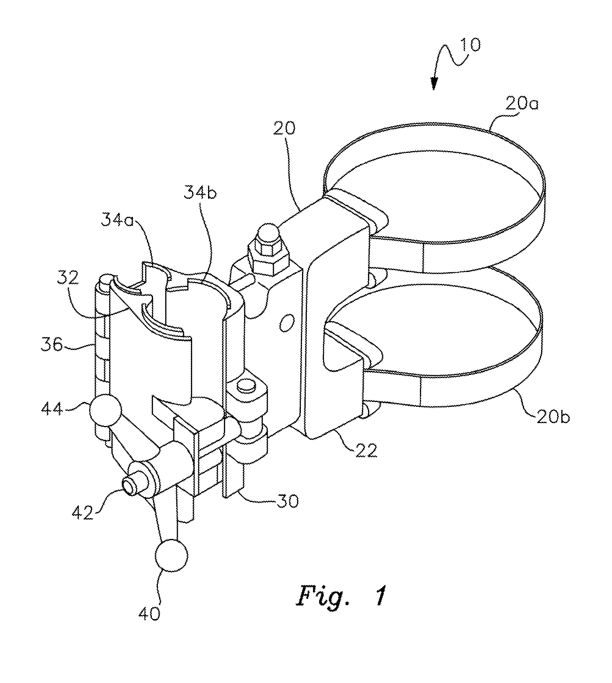
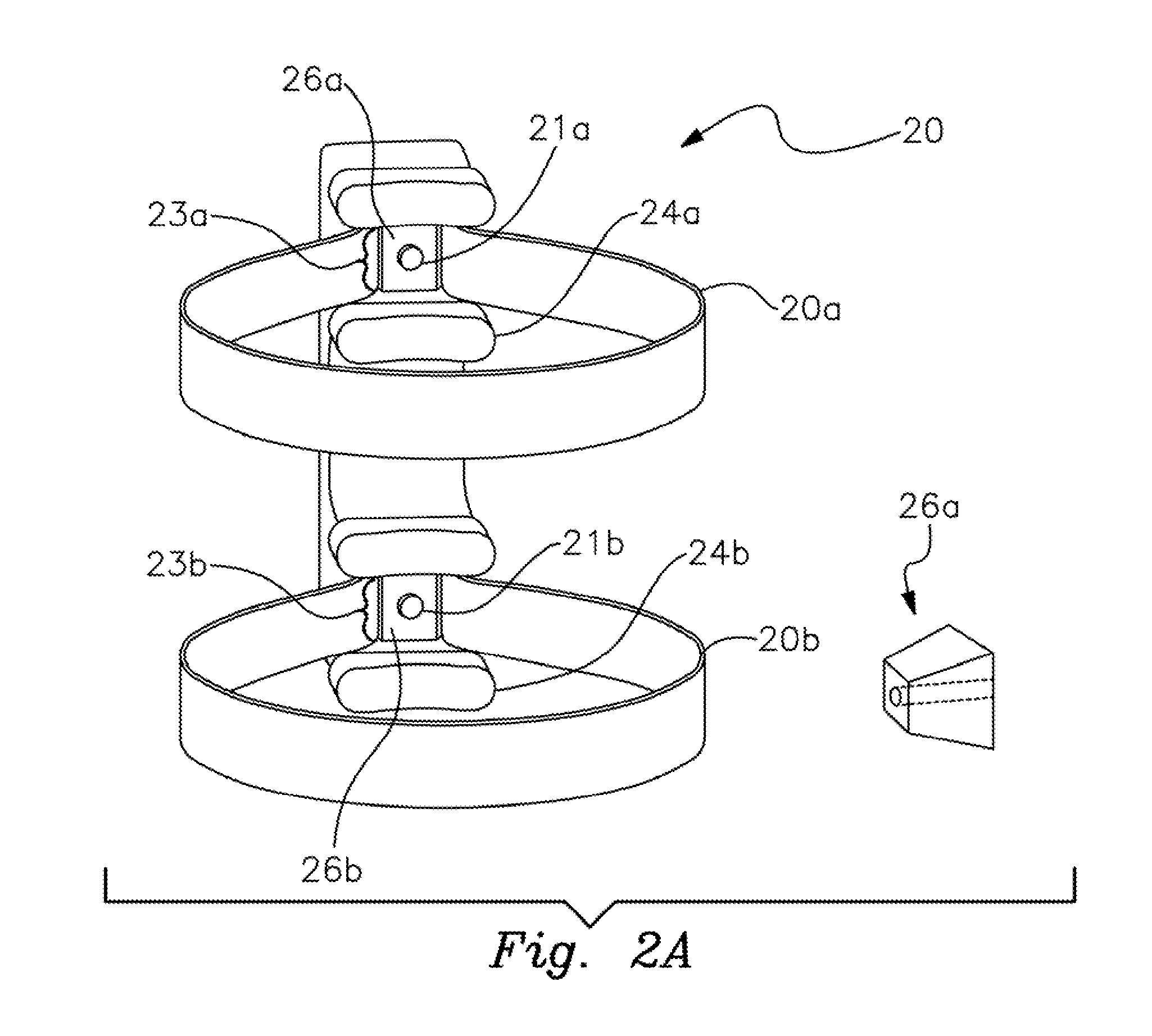
[0020]Referring now to FIG. 1, a perspective view of a preferred embodiment of the present application is illustrated. A coupling member 10 includes strapping assembly 20, communication grasp 30, and swivel assembly 42 for assisting in coupling a communication member (not shown) by communication grasp 30. In a preferred embodiment of the present application strapping assembly 20 includes opposing straps 20a and 20b that align substantially parallel to one another and are disposed to circumferentially surround another member such as a drill string or pipe component. Straps 20a and 20b may be of any of a variety of materials including composite, rubber, synthetic, or metallic. Strapping assembly 20 includes a bracket member 22 for coupling one or more straps 20a and 20b. Bracket member 22 includes receiving portions for drawing tension via straps 20a and 20b. Bracket member 22 includes grooves for adapting one or more straps 20a and 20b.

[0021]Communication grasp 30 couples to bracket...


PUM


Abstract

A clamp for placement about a riser having an assembly with a housing for releasably engaging at least one strap, the strap having a first and second end wherein the first and second ends are releasably attached to the housing, a plate on the housing for selectively engaging the first and second ends of the strap; and a support operably connected to the housing for releasably holding MUX, IWOC and other umbilical cables used in subsea applications. The housing may have two straps for engagement to a riser that shorten and lengthen by the turning of a screw through a plate engaged to the straps. The clamp may also have a hinged or fixed circular member for attachment around the riser. The cables are held by a hinged attachment to the housing that forms cylindrical vertical openings upon closure of the hinge.

Description

RELATED APPLICATION DATAClaim to Priority[0001]This application claims priority from U.S. Provisional Patent Application Ser. No. 61 / 299,547 entitled “Coupling Member” filed Jan. 29, 2010 and is incorporated by reference herein.FIELD OF THE INVENTION[0002]The present invention relates to coupling mechanisms for oil and gas processes and related apparatuses. More specifically the present application discloses an invention which is employed for coupling communication lines and other apparatuses which pertain to riser joints and those which allow control of blowout preventers (“BOP”) and other related wellhead control devices.BACKGROUND OF THE INVENTION[0003]Currently mechanisms which bind various well control lines to drill strings fall short of effectively coupling components which are used in drilling and production of oil, gas, and other minerals. Components which supply communication to various portions of BOPs, well heads, subsea production trees, and associated members often do ...

Claims


Application Information

Patent Timeline
Patent Type & Authority Applications(United States)
IPC IPC(8): F16L3/08
CPCF16L3/08
Inventor MCMILES, BARRYCATES, THOMAS
Owner THE SUBSEA
Why Eureka
Try Eureka