
Surface light source device and display device

a light source device and surface technology, applied in static indicating devices, lighting and heating apparatuses, instruments, etc., can solve problems such as deteriorating display image quality, and achieve the effect of improving display image quality

Inactive Publication Date: 2011-08-04
SATURN LICENSING LLC
View PDF4 Cites 7 Cited by
  • Summary
  • Abstract
  • Description
  • Claims
  • Application Information

AI Technical Summary

Benefits of technology

[0006]Here, in the above-described surface light source device of Patent Literature 1, a light-emission surface of each of the light guiding plates functions as a single partial lighting area, thereby realizing partial driving (local dimming) in which an in-plane light-emission intensity distribution in the surface light source device as a whole partially changes.
[0012]According to the surface light source device or the display device of the present invention, in each of the plurality of unit light-source sections being capable of mutually independent illumination, the uneven light-emission intensity distributions that are mutually independent are formed within the light-emission surface and thus, it is possible to form an arbitrary light-emission intensity distribution on the light-emission surface of each of the unit light-source sections. Therefore, by adjusting the light-emission intensity of each of the unit light-source sections, it is possible to make the appearance of a boundary between partial lighting areas more natural than related art. Further, in a display device having such a surface light source device, it is possible to improve display image quality further than related art.

Problems solved by technology

Consequently, a boundary between the partial lighting areas appears unnatural and thus, there has been such an issue that in, for example, use as a backlight source of a liquid crystal display, display image quality deteriorates.

Method used


Image

  • Surface light source device and display device
  • Surface light source device and display device
  • Surface light source device and display device

Examples


first embodiment

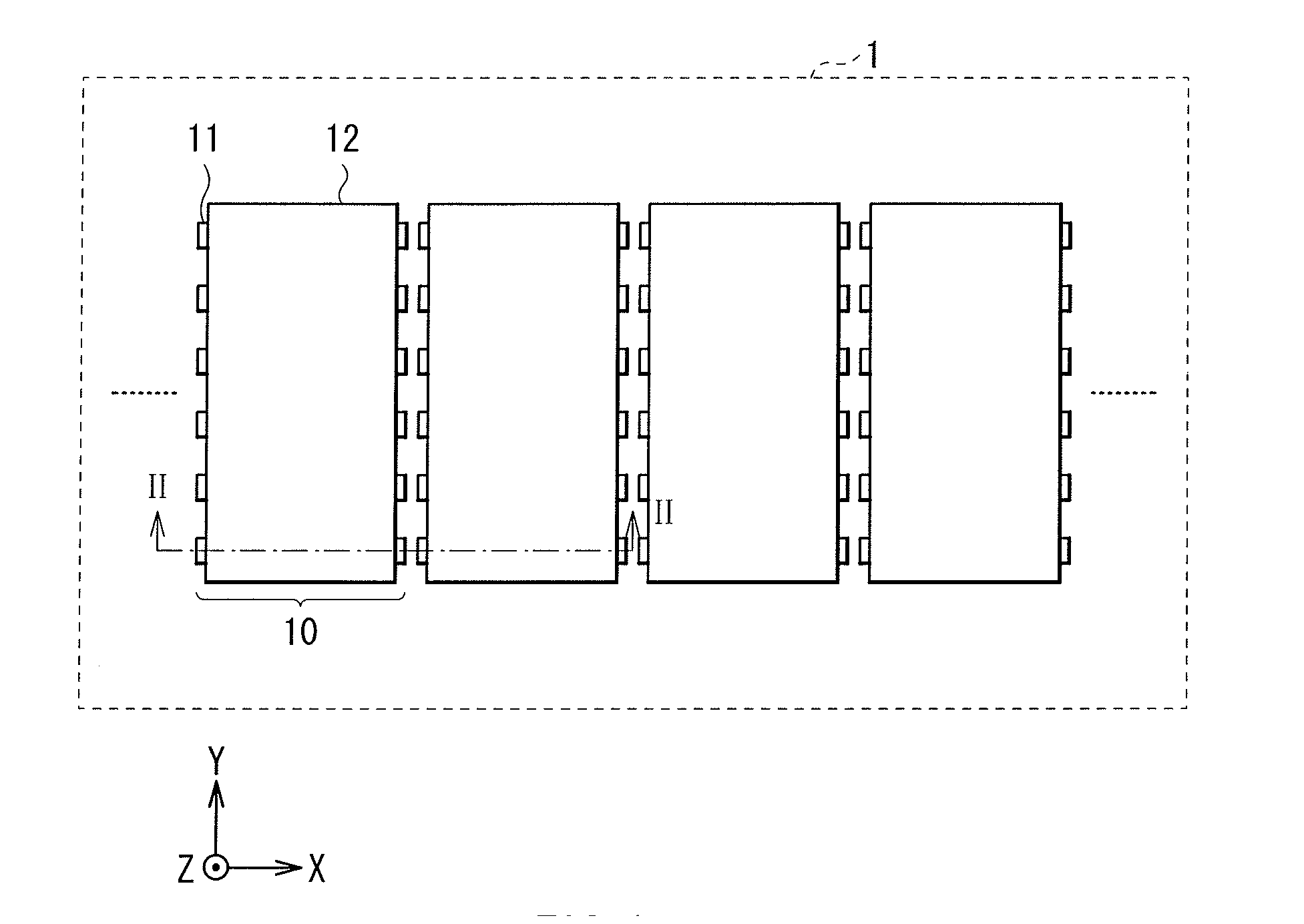
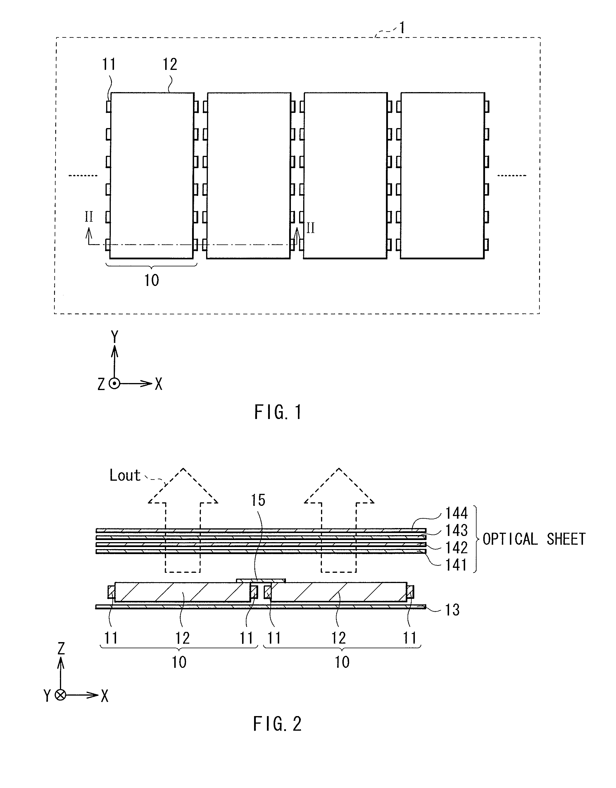
[0099]FIG. 1 illustrates a main structure of a surface light source device (a surface light source device 1) according to a first embodiment of the present invention in a plan view (X-Y plan view). Further, FIG. 2 illustrates a cross-sectional structure of the surface light source device 1 (a cross-sectional structure viewed along an arrow part II-II in FIG. 1) in a Z-X cross section. This surface light source device 1 is used, for example, as a backlight source for a display device such as a liquid crystal display, and is a light source that performs surface light emission with an X-Y plane serving as a light-emission surface. Further, in this light-emission surface, there are arranged plural unit light-source sections 10 capable of illuminating independently of one other (in FIG. 1, the plural unit light-source sections 10 are arranged along an X-axis direction).

[0100]Each of the unit light-source sections 10 is a light source section that emits emission light Lout in the normal d...

second embodiment

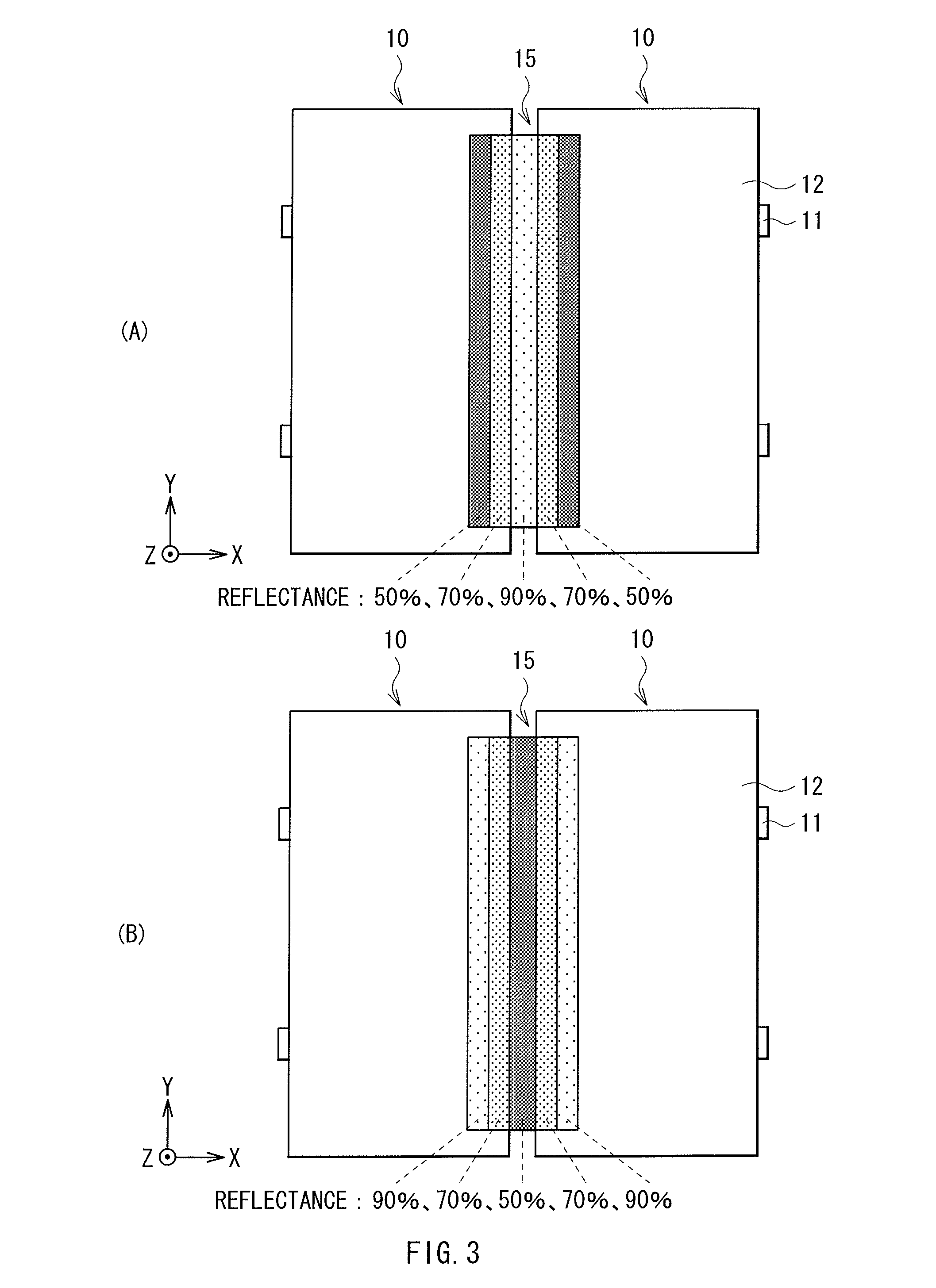
[0134]FIG. 44(A) and (B) illustrate an example of a light-emission mode of a unit light-source section 10K according to a second embodiment of the present invention. In this unit light-source section 10K, it is configured such that contrary to the unit light-source section 10 described above in the first embodiment, within the light-emission surface, from the side of the illuminating light source 11 to the opposite side, the light-emission intensity of the light emission of that light source 11 gradually increases.

[0135]Thus, as with the first embodiment, the uneven light-emission intensity distribution by the light emission of the light source 11 on the one side (the uneven light-emission intensity distribution on the left side of FIG. 44(B)) and the uneven light-emission intensity distribution by the light emission of the light source 11 on the other side (the uneven light-emission intensity distribution in the middle of FIG. 44(B)) are superimposed, and thereby it is possible to ...

third embodiment

[0168]FIG. 65 illustrates an example of a light-emission mode of the unit light-source section 10 (or the unit light-source section 10K) according to a third embodiment of the present invention. In this unit light-source section 10 (10K), in each of the light guiding plates 12, it is possible to set, along a side where the plural light sources 11 are arranged (here, a side in an X-axis direction), the light-emission intensities of the respective light sources 11 independently of each other. Thus, in the unit light-source section 10 (10K) illustrated in FIG. 66, the light-emission intensities of the light sources 11 are set to change gradually along the side where the light sources 11 are arranged (here, the side in the X-axis direction), and a light-emission intensity distribution is adjusted along that direction.

[0169]Therefore, as illustrated in, for example, FIG. 66 and FIG. 67, by combination with the structure in which in a manner similar to that described in the first embodime...


PUM


Abstract

There is provided a surface light source device capable of making appearance of a boundary between partial lighting areas more natural than related art. In each of unit light-source sections 10 capable of mutually independent lighting, uneven light-emission intensity distributions that are mutually independent are to be formed within a light emission surface. Thus, in the light emission surface of each of the unit light-source sections 10, an arbitrary light-emission intensity distribution is able to be formed. Therefore, by adjusting a light-emission intensity distribution of each of the unit light-source sections 10, the appearance in the boundary between the partial lighting areas becomes more natural than related art.

Description

TECHNICAL FIELD[0001]The present invention relates to a surface light source device that performs surface light emission with use of light guiding plate and a display device having such a surface light source device.[0002]This application is based upon and claims the benefit of priority of the prior Japanese Patent Application No. 2008-163848, filed on Jun. 23, 2008 in Japan, the contents of which are cited herein by reference.BACKGROUND ART[0003]In the past, various devices have been proposed and commercialized as a surface light source device such as a backlight source applied to, for example, a liquid crystal display.[0004]For example, in Patent Literature 1, there is proposed a surface light source device in which plural light guiding plates are arranged. In this surface light source device, plural light sources are arranged on sides of each of the light guiding plates.CITATION LISTPatent Literature[0005]Patent Literature 1: Japanese Unexamined Patent Application Publication No....

Claims


Application Information

Patent Timeline
IPC IPC(8): G02F1/13357G09G3/36F21V8/00
CPCG02B6/0045G02B6/0068G02F2001/133601G02F1/133603G02B6/0078G02F1/133601
Inventor SUZUKI, HIROMASA
Owner SATURN LICENSING LLC
Learn More