Dongle transceiver and antenna assembly

a transceiver and antenna technology, applied in the field of wireless communication systems, can solve the problem of not being able to implement in the substantially two-dimensional space of the substra

Inactive Publication Date: 2011-08-04
AVAGO TECH INT SALES PTE LTD
View PDF8 Cites 46 Cited by
  • Summary
  • Abstract
  • Description
  • Claims
  • Application Information

AI Technical Summary

Problems solved by technology

An issue with such three-dimensional antennas is that they cannot be implemented in the substantially two-dimensional

Method used


Image

  • Dongle transceiver and antenna assembly
  • Dongle transceiver and antenna assembly
  • Dongle transceiver and antenna assembly

Examples


Embodiment Construction

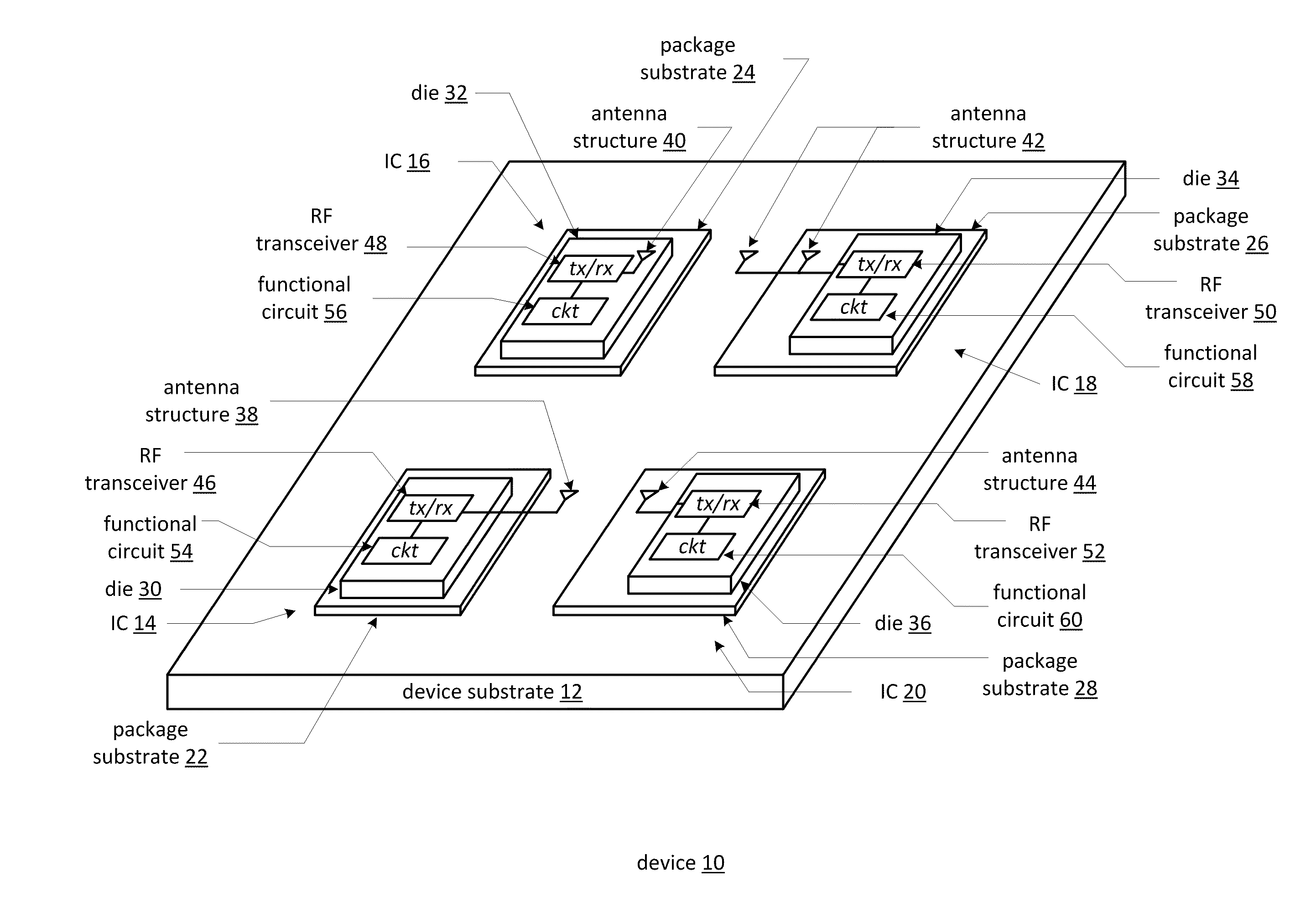
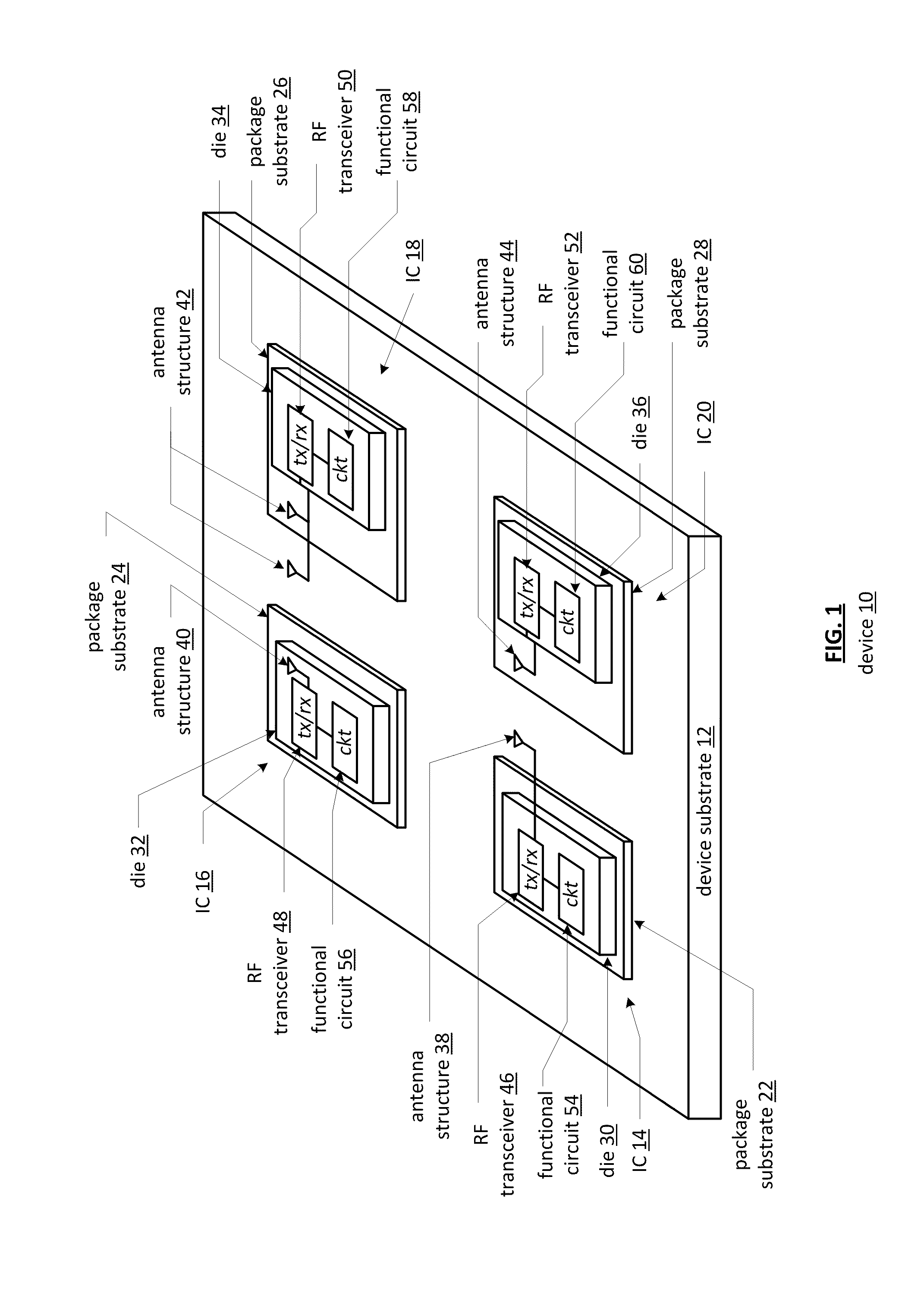
[0036]FIG. 1 is a diagram of an embodiment of a device 10 that includes a device substrate 12 and one or more circuits 14-20 (four shown). Each of the circuits (which may be fabricated on the substrate 12 or as ICs) includes a circuit module 56, a transceiver circuit 48, a transmit / receive switch (shown in one or more subsequent figures), a decoupling module (shown in one or more subsequent figures), and an antenna structure 40 (which may be a multiple input multiple output (MIMO) antenna structure).

[0037]If the circuits are fabricated as ICs, then they include a package substrate 22-28 a die 30-36 where some or all of the other components are on the die or substrate. For example, die 30 of circuit 14 includes a functional circuit 54 and a transceiver circuit 46 coupled to an antenna structure 38 on the substrate 12. Die 32 of circuit 16 includes an antenna structure 40, an RF transceiver 48, and a functional circuit 56. Die 34 of circuit 18 includes an RF transceiver 50 and a funct...


PUM


Abstract

A dongle transceiver a substrate, a transceiver circuit, a transmit/receive switch, a MIMO antenna structure, and a decoupling module. The transceiver circuit is on at least one of the first and second sides of the substrate and is coupled to the transmit/receive switch. The MIMO antenna structure is on at least one of the first and second sides of the substrate. The decoupling module is on at least one of the first and second sides of the substrate, couples the MIMO antenna structure to the transmit/receive switch, and electrically isolates antennas of the MIMO antenna structure.

Description

CROSS REFERENCE TO RELATED PATENTS[0001]The present U.S. Utility Patent Application claims priority pursuant to 35 U.S.C. §119(e) to the following U.S. Provisional Patent Applications which are hereby incorporated herein by reference in their entirety and made part of the present U.S. Utility Patent Application for all purposes:[0002]1. U.S. Provisional Application Ser. No. 61 / 322,865, entitled “2.4 GHZ MIMO 2×2 Dongle Antenna Structure,” (Attorney Docket No. BP21429), filed Apr. 11, 2010, pending; and[0003]2. U.S. Provisional Application Ser. No. 61 / 300,351, entitled “High Isolation MIMO Antenna Structure,” (Attorney Docket No. BP21651), filed Feb. 1, 2010, pending.STATEMENT REGARDING FEDERALLY SPONSORED RESEARCH OR DEVELOPMENT[0004]NOT APPLICABLEINCORPORATION-BY-REFERENCE OF MATERIAL SUBMITTED ON A COMPACT DISC[0005]NOT APPLICABLEBACKGROUND OF THE INVENTION[0006]1. Technical Field of the Invention[0007]This invention relates generally to wireless communication systems and more par...

Claims


Application Information

Patent Timeline
IPC IPC(8): H04B1/38
CPCH04B1/38H01Q21/28H01Q1/521
Inventor YOON, SEUNGHWANALEXOPOULOS, NICOLAOS G.CASTANEDA, JESUS
Owner AVAGO TECH INT SALES PTE LTD
Why Eureka
Try Eureka