Receiving apparatus and image rejection method

a receiver and image technology, applied in the direction of electrical equipment, transmission, etc., can solve the problems of large increase in difficulty in ensuring the orthogonality of both desired signal and image signal, and achieve the effect of greatly increasing iq mismatch of image signal

Inactive Publication Date: 2011-08-04
RENESAS ELECTRONICS CORP
View PDF6 Cites 21 Cited by
  • Summary
  • Abstract
  • Description
  • Claims
  • Application Information

AI Technical Summary

Benefits of technology

[0016]As described above, by using the complex filter, there is produced a difference between the IQ mismatch of the desired signal and the IQ mismatch of the image signal. More specifically, the IQ mismatch of the image signal is greatly increased compared with the IQ mismatch of the desired signal. The first exemplary aspect of the present invention addresses with this problem by adjusting the element characteristic of the element included in the complex filter, thereby compensating the IQ mismatch of the image signal. Further, the IQ mismatch of the desired signal is compensated using an orthogonal compensation circuit arranged at a subsequent stage of the complex filter. In summary, the first exemplary aspect of the present invention performs the IQ mismatch compensation for the image signal, which is difficult to address only in the subsequent stage side of the complex filter, by element adjustment in the complex filter, and performs the IQ mismatch compensation for the desired signal in the subsequent stage of the complex filter. Accordingly, both of the IQ mismatch of the desired signal and the IQ mismatch of the image signal having different magnitude with each other can be compensated.
[0017]The first exemplary aspect of the present invention described above makes it possible to maintain the orthogonality of both of the desired signal and the image signal when the complex filter and the image rejection configuration such as the Weaver architecture or the Hartley architecture are combined.

Problems solved by technology

However, when the complex filter is further used, it is difficult to ensure the orthogonality of both of the desired signal and the image signal with this method.
More specifically, the IQ mismatch of the image signal is greatly increased compared with the IQ mismatch of the desired signal.

Method used


Image

  • Receiving apparatus and image rejection method
  • Receiving apparatus and image rejection method
  • Receiving apparatus and image rejection method

Examples


first exemplary embodiment

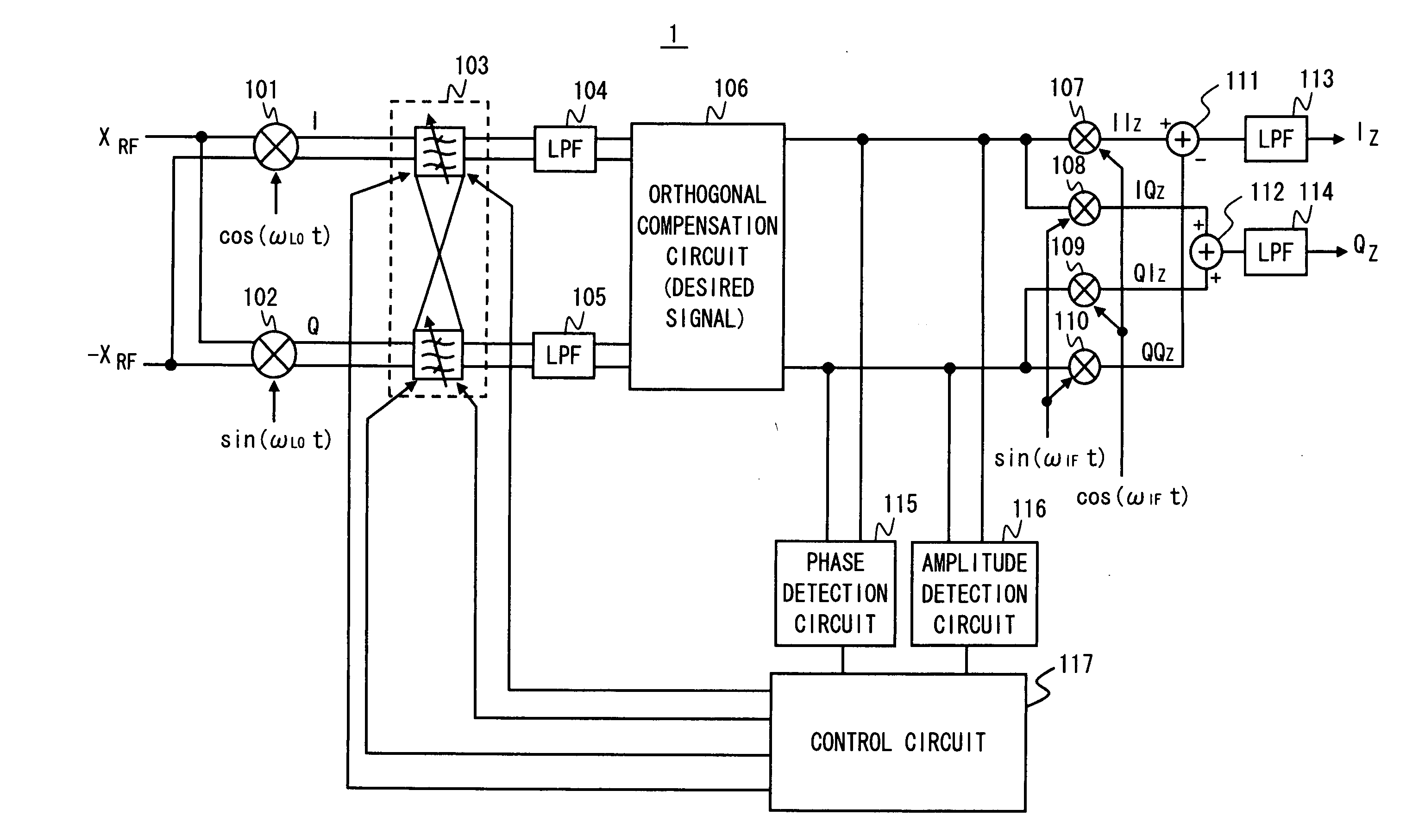
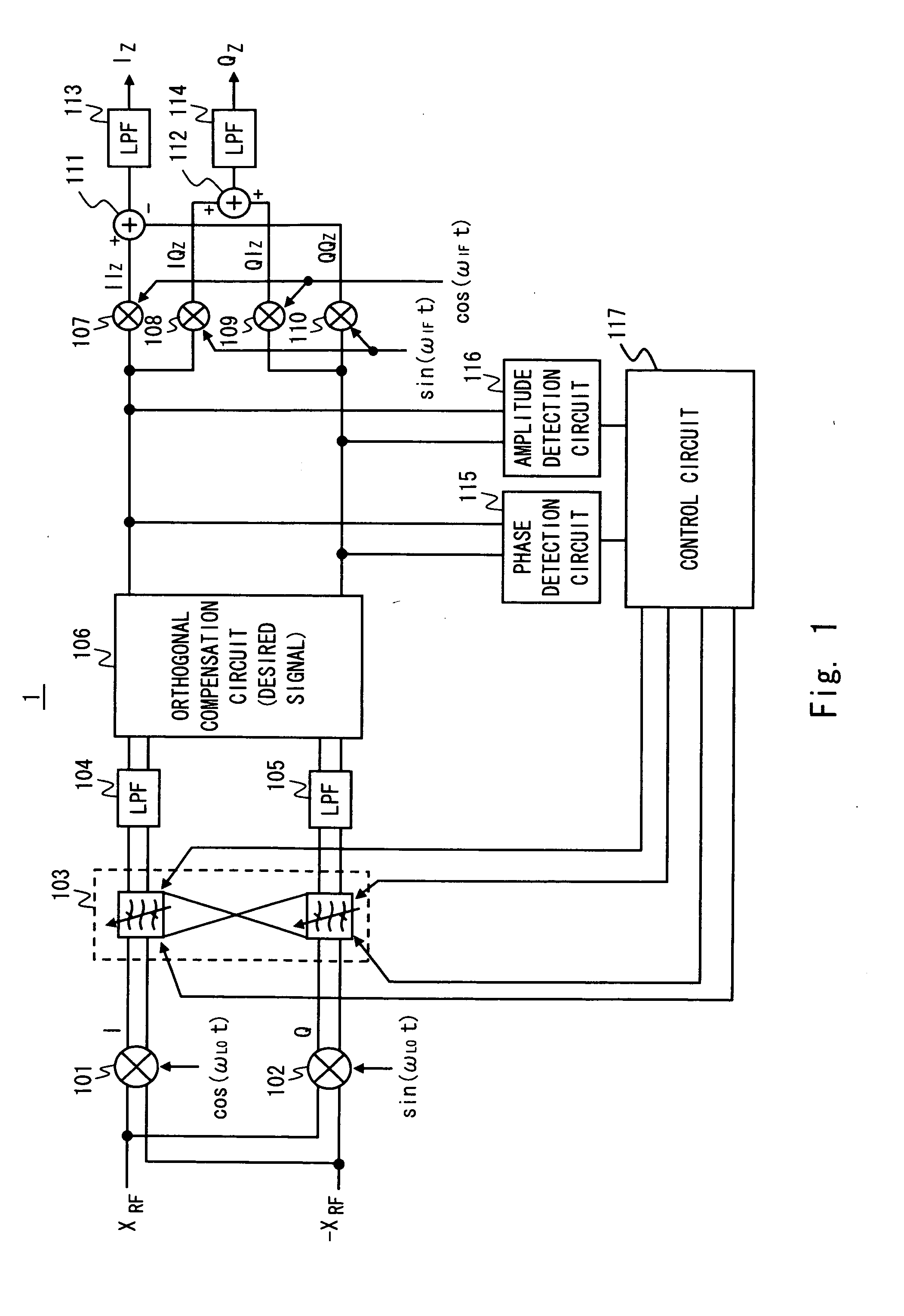
[0027]FIG. 1 is a block diagram showing a configuration example of an image rejection receiver 1 according to a first exemplary embodiment of the present invention. The receiver 1 shown in FIG. 1 performs image suppression by a complex filter and image rejection by the Weaver architecture by combining them. More specifically, a complex filter 103 is arranged between a first orthogonal mixer (mixers 101 and 102) and a second orthogonal mixer (mixers 107 and 110, and mixers 108 and 109).

[0028]The mixer 101 shown in FIG. 1 multiplies differential RF signals (XRF and −XRF) by a local signal (cos(ωLOt)), so as to generate an in-phase signal (I signal) of IF bandwidth. The mixer 102 multiplies differential RF signals (XRF and −XRF) by a local signal (sin(ωLOt)), so as to generate an orthogonal signal (Q signal) of IF bandwidth.

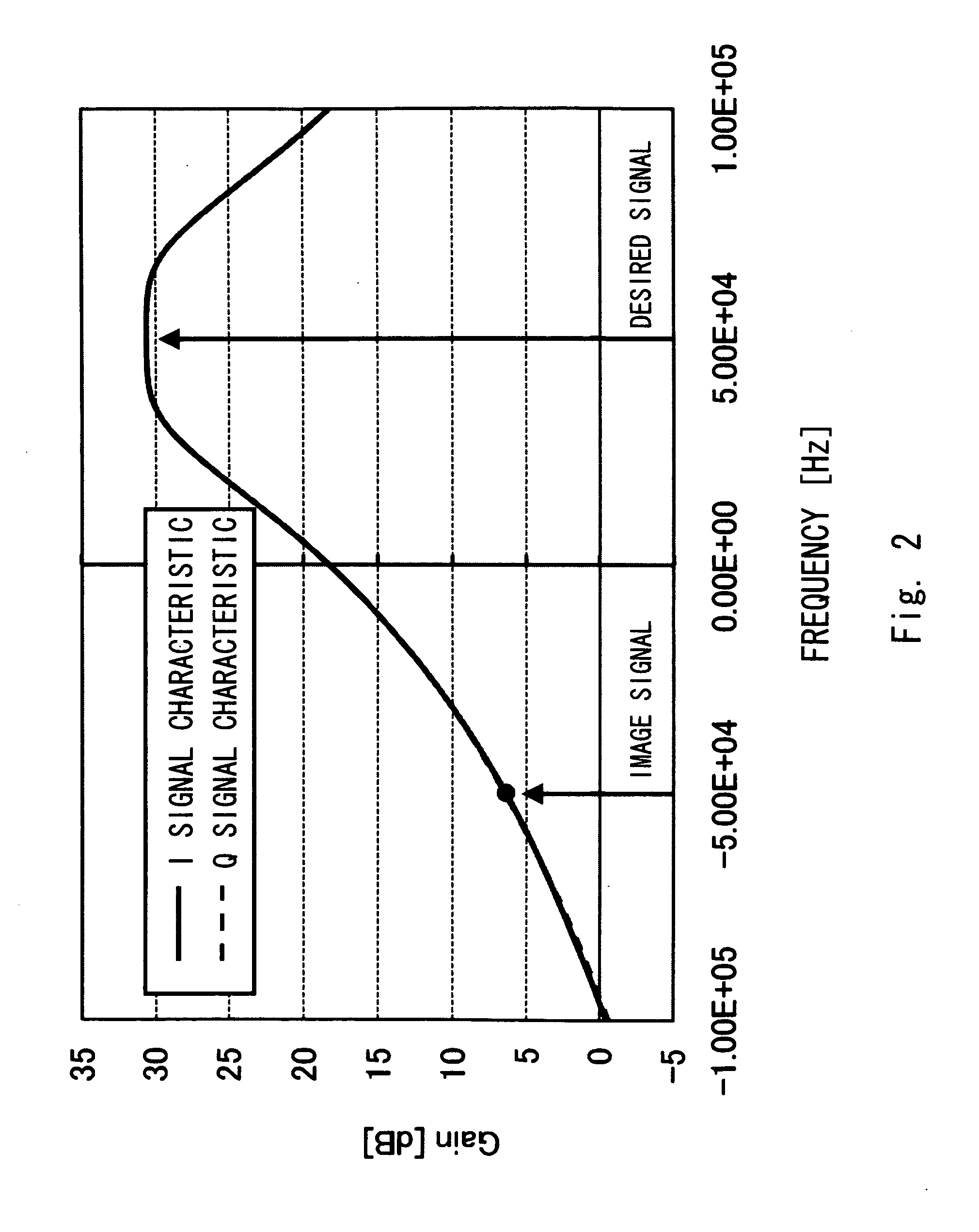
[0029]The complex filter 103 has an asymmetrical frequency gain property between a positive frequency domain and a negative frequency domain. The complex filter 103...

exemplary embodiment 1

Other Exemplary Embodiment 1

[0054]Although the Weaver architecture and the complex filter have been combined in the first exemplary embodiment, the Hartley architecture may be used instead of using the Weaver architecture. In this case, the orthogonal mixing operation performed in the second-stage mixers 107 to 110 may be replaced with the 90-degree phase shift operation using the phase circuit.

exemplary embodiment 2

Other Exemplary Embodiment 2

[0055]The arrangement of the orthogonal compensation circuit 106 is not limited between the complex filter 103 and the second-stage mixers 107 to 110. For example, the orthogonal compensation circuit 106 may be arranged in the subsequent stage of the LPFs 113 and 114. When an analog modulation signal is received and the signal is down-converted by the second-stage mixers 107 to 110 to around DC, the orthogonal compensation circuit 106 is preferably arranged in the IF frequency section as shown in FIG. 1, whereby the phase rotation of the I signal and the Q signal can be observed and the phase difference deviation in the desired signals can be easily detected.


PUM


Abstract

An orthogonal mixer generates first I and Q signals by down-converting an RF signal. A complex filter has an asymmetrical frequency gain property between a positive frequency domain and a negative frequency domain, and generates second I and Q signals by suppressing image signals included in the first I and Q signals compared with desired signals. An orthogonal compensation circuit is located at a subsequent stage of the complex filter, and corrects the second I and Q signals to cancel a phase difference error and an amplitude error of the desired signals between the second I and Q signals. Further, a control circuit adjusts an element characteristic of the complex filter to cancel a phase difference error and an amplitude error of the image signals that appear in the second I and Q signals.

Description

INCORPORATION BY REFERENCE[0001]This application is based upon and claims the benefit of priority from Japanese patent application No. 2010-020453, filed on Feb. 1, 2010, the disclosure of which is incorporated herein in its entirety by reference.BACKGROUND[0002]1. Field of the Invention[0003]The present invention relates to an image rejection in a superheterodyne receiver.[0004]2. Description of Related Art[0005]The Hartley architecture and the Weaver architecture are known as image rejection schemes in a superheterodyne receiver. The Hartley architecture and the Weaver architecture are image rejection schemes using the fact that a desired signal and an image signal are located opposite to each other with respect to a local frequency. The Hartley architecture and the Weaver architecture execute a phase shift operation on an Intermediate Frequency (IF) signal after being orthogonal down-converted, thereby providing different phase shifts to the desired signal and the image signal. A...

Claims


Application Information

Patent Timeline
Patent Type & Authority Applications(United States)
IPC IPC(8): H04B1/10
CPCH04B1/10H04B1/30
Inventor OHSHIRO, MASAYOSHI
Owner RENESAS ELECTRONICS CORP
Why Eureka
Try Eureka