Scheme for Operating an Electric Window Lifter

a technology of electric window lifter and operating system, which is applied in the direction of door/window fittings, wing accessories, transportation and packaging, etc., can solve the problem of parts of the body or objects being trapped, and achieve the effect of preventing damage/injury

Inactive Publication Date: 2011-08-11
BROSE FAHRZEUGTEILE GMBH & CO KG HALLSTADT (DE)
View PDF30 Cites 10 Cited by
  • Summary
  • Abstract
  • Description
  • Claims
  • Application Information

AI Technical Summary

Benefits of technology

According to an advantageous development, in the case of trapping the front side pane (front pane) on the same side as the rear pane, i.e. that on the same side of the vehicle (driver or passenger side), is held in position at the same time as

Problems solved by technology

As the front edge approaches the B pillar or the fro

Method used


Image

  • Scheme for Operating an Electric Window Lifter
  • Scheme for Operating an Electric Window Lifter
  • Scheme for Operating an Electric Window Lifter

Examples


Embodiment Construction

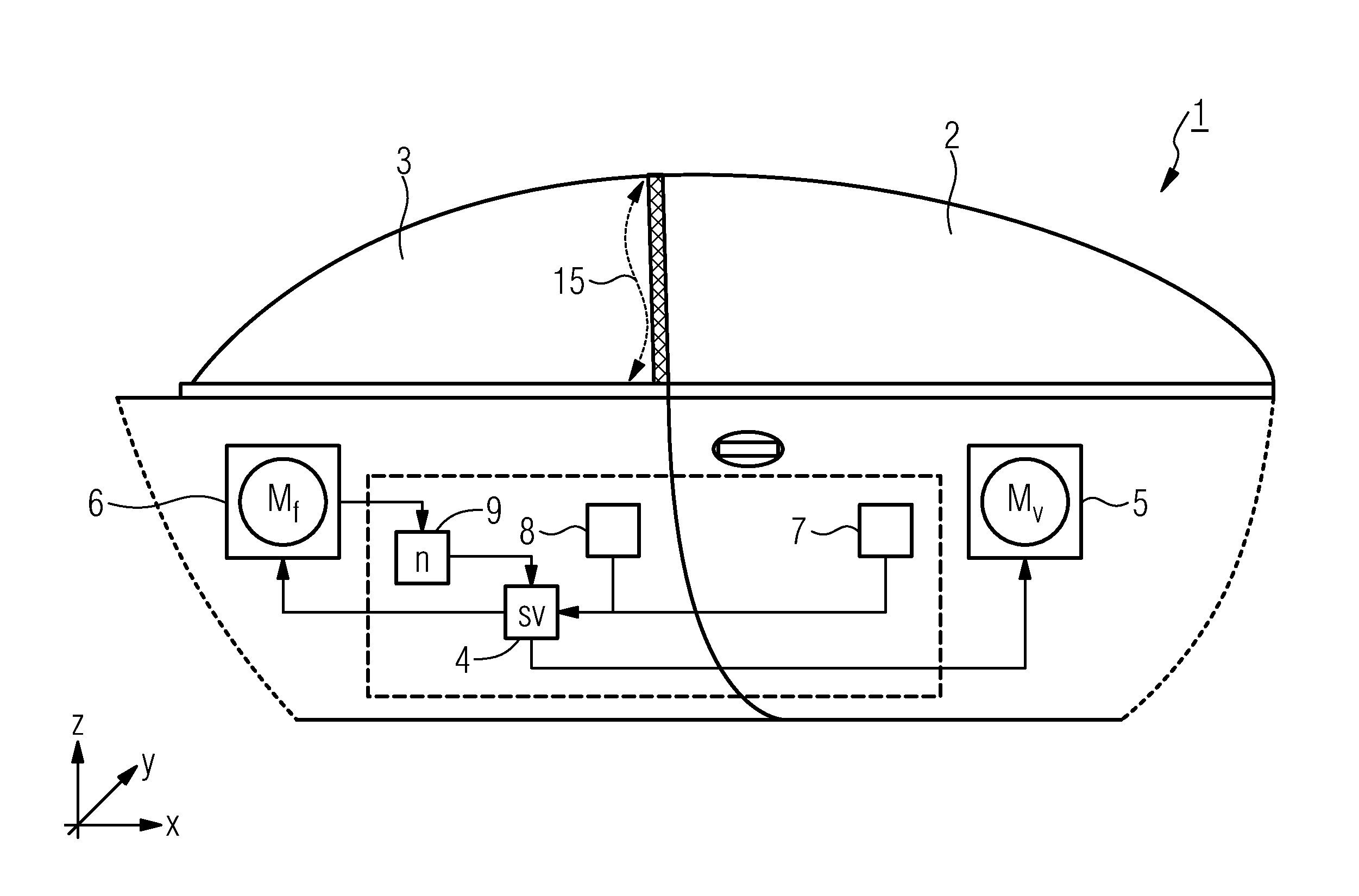
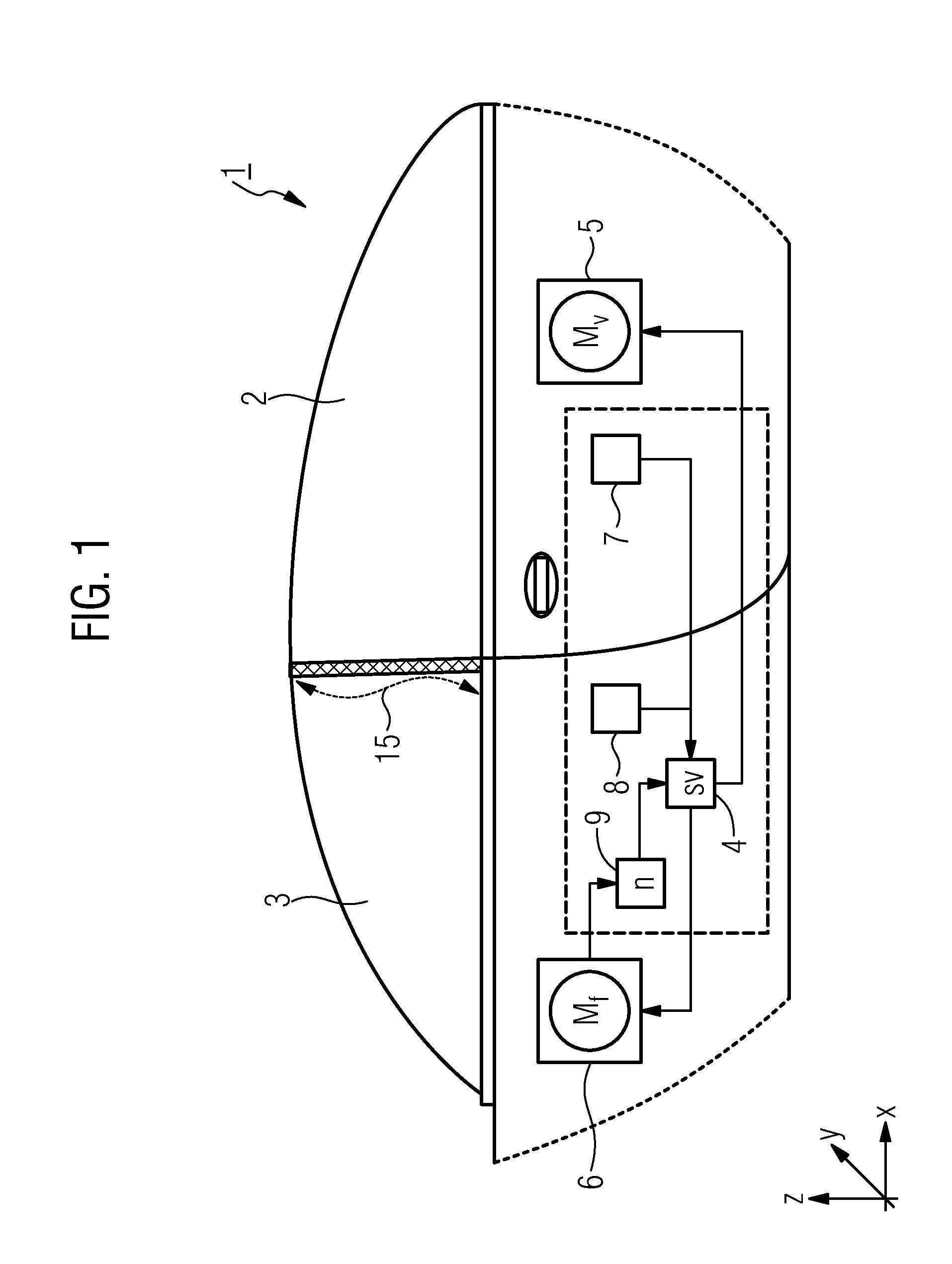
FIG. 1 shows a side part 1 of a motor vehicle with a movable front pane 2 and a movable rear pane 3 and, in schematic representation, a control device 4 for operating a front window lifter motor 5 and a rear window lifter motor 6. In this case, a front window lift button 7 and a rear window lift button 8 are connected to the control device 4. The front and rear window lifter motors 5, 6 are furthermore connected to the control device 4. A rotation speed monitor 9 is connected to the rear window lifter motor 6 and to the control device 4.

When the front or rear window lift button 7, 8 is actuated, the front or rear window lifter motor 5, 6 is operated by the control device 4. In this case, the front pane 2 or rear pane 3 is moved in accordance with a button command. During the movement of the rear pane 3, the rotation speed monitor 9 records the rotation speed n of the rear window lifter motor 6, and the control device 4 analyzes the rotation speed n in order to detect a case of trapp...


PUM


Abstract

The invention relates to an operating method for an electric window lifter for moving a rear pane (3) in a motor vehicle, in which the rear pane (3) is moved in a lowering direction (−z) along an approximately s-shaped path of movement. In the case of trapping, the movement of the rear pane (3) in the lowering direction (−z) is stopped and the rear pane (3) is moved in the lifting direction (+z).

Description

BACKGROUND1. Field of the InventionThe invention relates to an operating method for an electric window lifter for moving a rear pane. The invention furthermore relates to a control device for carrying out the method.2. Description of the Related ArtElectric window lifters are installed in vehicles and, in response to a control command, move the vehicle panes, in particular also a “rear pane”, into a desired position. The term rear pane is understood to mean a side pane in a vehicle, arranged behind what is referred to as the B pillar or adjoining a front pane associated with the driver's or passenger's door on the same side. When closed, a front edge of the rear pane adjoins the B pillar. The term vehicle “B pillar” is generally used to refer to the connecting pillar between the vehicle floor and the vehicle roof, approximately in the middle of a passenger compartment. Many coupés or cabriolets do not have a B pillar. In the case of such vehicles without a B pillar, the front edge o...

Claims


Application Information

Patent Timeline
IPC IPC(8): E05F15/08B60J1/17
CPCE05F11/525E05Y2900/55B60J1/17B60J1/18E05F15/73E05F15/41E05F15/42E05F15/695E05F15/646
Inventor ZELLMER, RENEKALB, ROLAND
Owner BROSE FAHRZEUGTEILE GMBH & CO KG HALLSTADT (DE)
Why Eureka
Try Eureka