Coupling system, assembly of an equipment rigidly connected to a user and a coupling system and kiteboarding kite bar

a coupling system and equipment technology, applied in the field of sports, can solve the problems of high manufacturing cost, large distance between the kiteboarder and the kiteboard bar, and the central body of the single-piece release system is a very complex part, and achieve the effect of reducing manufacturing cos

Active Publication Date: 2021-06-15
ROGER SA
View PDF8 Cites 0 Cited by
  • Summary
  • Abstract
  • Description
  • Claims
  • Application Information

AI Technical Summary

Benefits of technology

[0010]The present invention seeks to resolve the drawbacks of the state of the art by proposing a coupling system for coupling a piece of equipment rigidly connected to a user with at least one rigging strand comprising a central body made up of two parts configured to be assembled with one another via an attachment means, which allows natural stripping of the central body and therefore reduces manufacturing cost of the central body mold, which no longer needs drawers.
[0011]The invention also proposes an assembly of an equipment rigidly connected to a user and a coupling system, and a kiteboarding kite bar comprising the coupling system according to the invention making it possible to release the kiteboarding kite in case of emergency.

Problems solved by technology

However, the single-piece type central body of the existing release systems is a very complex part that is expensive to manufacture, since it requires creating a very costly mold with drawers for stripping the central body.
As a result, there is a great distance between the kiteboarder and the kiteboarding kite bar, due to the release system that is inserted between the two.
Yet the shorter the release system is, the more the kiteboarder will be able to depower the sail and therefore quickly and easily reduce the power of the kiteboard.
Thus, currently, and above all when the kiteboarders use a belt-type harness, they cannot easily depower the sail, the kiteboarder having, as a reminder, to push the bar far away from him to depower the kiteboard and reduce its power.
Furthermore, the short people who use a belt-type harness are often at arms' length when the kiteboard retains power, the height of the release system then limiting their ability to depower.
The central body of the existing release systems generally comprises a central hole that is often too narrow, and makes it difficult to pass the safety line, and in particular the junction between the safety line and the kite line, if the assembly was designed on the front line.
Thus, many manufacturers avoid passing the safety line inside the central body, which leads to not completely depowering the sail in case of emergency release and may prove highly problematic in terms of safety.

Method used


Image

  • Coupling system, assembly of an equipment rigidly connected to a user and a coupling system and kiteboarding kite bar
  • Coupling system, assembly of an equipment rigidly connected to a user and a coupling system and kiteboarding kite bar
  • Coupling system, assembly of an equipment rigidly connected to a user and a coupling system and kiteboarding kite bar

Examples


first embodiment

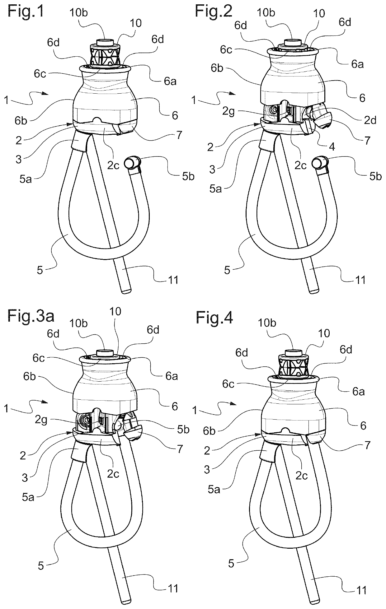
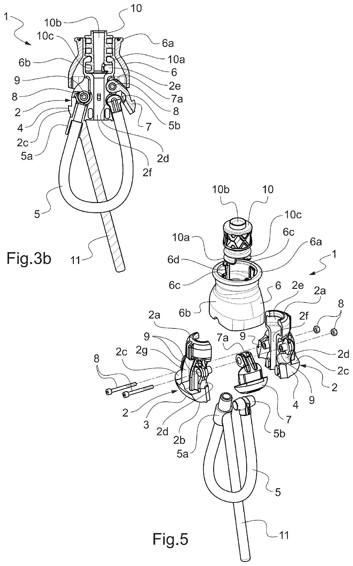
[0094]FIGS. 1, 2, 3a, 3b, 4 and 5 show a coupling system 1 according to the present invention.

[0095]The coupling system 1 for coupling a piece of equipment rigidly connected to a user, such as a harness, to at least one rigging strand, for example connected to a kiteboarding kite, comprises a central body 2 made up of two parts 3 and 4 configured to be assembled to one another by an attachment means that will be described in more detail hereinafter, the central body 2 having a rigging strand side end 2a and an opposite user side end 2b.

[0096]Designing the central body 2 in two parts 3 and 4 allows natural stripping of the central body 2 during its design, and therefore reduces the manufacturing cost of the corresponding mold, which no longer needs to have drawers.

[0097]The coupling system 1 further comprises a fastener 5 comprising two ends 5a and 5b. The fastener 5 is made up of a rope or cable covered with a tube of the polyvinyl chloride (PVC), polyurethane, or thermoplastic pol...

second embodiment

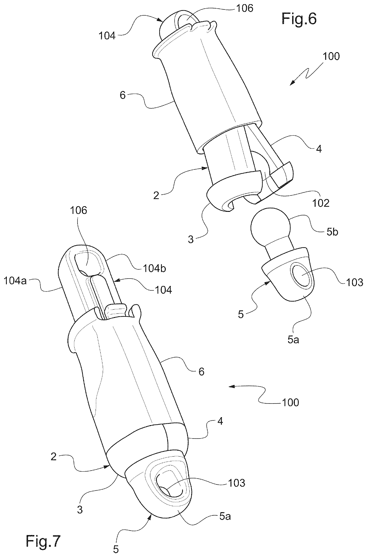
[0146]FIGS. 6, 7 and 8 show a coupling system 100 according to the present invention.

[0147]The elements that are shared between the first embodiment of the invention and this second embodiment of the invention bear the same reference numerals and will not be described in more detail here when they have identical structures.

[0148]In this second embodiment of the invention, the fastener second end 5b blocking means is made up of the two parts 3, 4 of the central body 2, which are symmetrical and connected to one another by a rotation axis at the rigging strand side end 2a of the central body 2.

[0149]Said rotation axis is formed by a nut-screw assembly 8, the screw of the nut-screw assembly 8 passing through a hole 101 formed in each part 3, 4 of the central body 2 at the rigging strand side end 2a. The two parts 3 and 4 of the central body 2 can thus move away from one another, by rotation around said rotation axis, when the shell 6 is pushed by the user away from the latter.

[0150]The...


PUM


Abstract

Disclosed is a coupling system for coupling a piece of equipment rigidly connected to a user with at least one rigging strand, including a central body made of two parts configured to be assembled with one another via an attachment unit, a fastener including two ends, a shell configured to at least partially cover the side surface of the central body, and at least one lock configured to engage with the shell in order to releasably lock the second end of the fastener, the shell being movable in translation over the side surface of the central body and being connected to the central body via at least one elastic recall component.

Description

BACKGROUND OF THE INVENTIONField of the Invention[0001]The present invention relates to the sports field of kiteboards, and more generally the nautical field, and in particular relates to a coupling system for coupling a piece of equipment rigidly connected to a user to at least one rigging strand connected, for example, to a kiteboarding kite, to an assembly of an equipment rigidly connected to a user and a coupling system, and to a kiteboarding kite bar.[0002]Kiteboarding is a gliding sport consisting in moving with a board on the surface of a body of water while being pulled by a specially designed kite, called kite or sail. The kiteboarder, coupled to the kite by a harness, steers the kiteboard using a bar to which the traction lines of the kite are connected.[0003]A release system on which the harness is fastened makes it possible, in case of emergency, to cancel the power of the kite by releasing the harness when the kiteboarder actuates said release system by detaching the lo...

Claims


Application Information

Patent Timeline
Patent Type & Authority Patents(United States)
IPC IPC(8): F16B45/00B63H8/16B64C31/028
CPCB63H8/16F16B45/00B64C31/0285B63H8/18B63H8/56F16B45/008
Inventor ROGER
Owner ROGER SA
Why Eureka
Try Eureka