
Screen printer

a screen printer and printer body technology, applied in office printing, coatings, printed circuits, etc., can solve the problems of screen printers, troublesome stencil mask change operation, and increase the number of manual operations during equipment managemen

Active Publication Date: 2011-08-11
HANWHA AEROSPACE CO LTD
View PDF9 Cites 29 Cited by
  • Summary
  • Abstract
  • Description
  • Claims
  • Application Information

AI Technical Summary

Benefits of technology

[0013]One or more exemplary embodiments address aforementioned aspects associated with the related-art screen printer by providing a screen printer capable of separately forming at least one introduction and extraction portion of which a dimension, such as width and height, is similar to a corresponding dimension of a stencil mask without a separate open-type cover, counting a preset standby time when introduction of the stencil mask is detected and semi-automatically introducing the stencil mask through the at least one introduction and extraction portion, preventing the temperature inside the screen printer from being abnormally varied by an external temperature, normally maintaining the operation performance of the screen printer, and reducing the number of manual operations, in which an operator introduces the stencil mask into the screen printer because there is no need for manual operations of opening / closing the cover provided in the related-art screen printer.

Problems solved by technology

However, in the related-art screen printer, after an operator opens the cover, since the operation of introducing a new stencil mask through the open portion must be performed, the number of manual operations during equipment management increases, and the stencil mask change operation becomes very troublesome.
In addition, while temperature in the screen printer must be uniformly maintained, when the operator opens the cover of the screen printer to change the stencil mask with a new one, the temperature in the screen printer becomes affected by external temperatures different therefrom, decreasing operation performance of the screen printer and causing operation error.

Method used


Image

  • Screen printer
  • Screen printer
  • Screen printer

Examples


Embodiment Construction

[0031]Exemplary embodiments will now be described more fully hereinafter with reference to the accompanying drawings.

[0032]The inventive concept may, however, be embodied in different forms and should not be construed as limited to the exemplary embodiments set forth herein. Rather, these exemplary embodiments are provided so that this disclosure will be thorough and complete, and will fully convey the scope of the inventive concept to those skilled in the art.

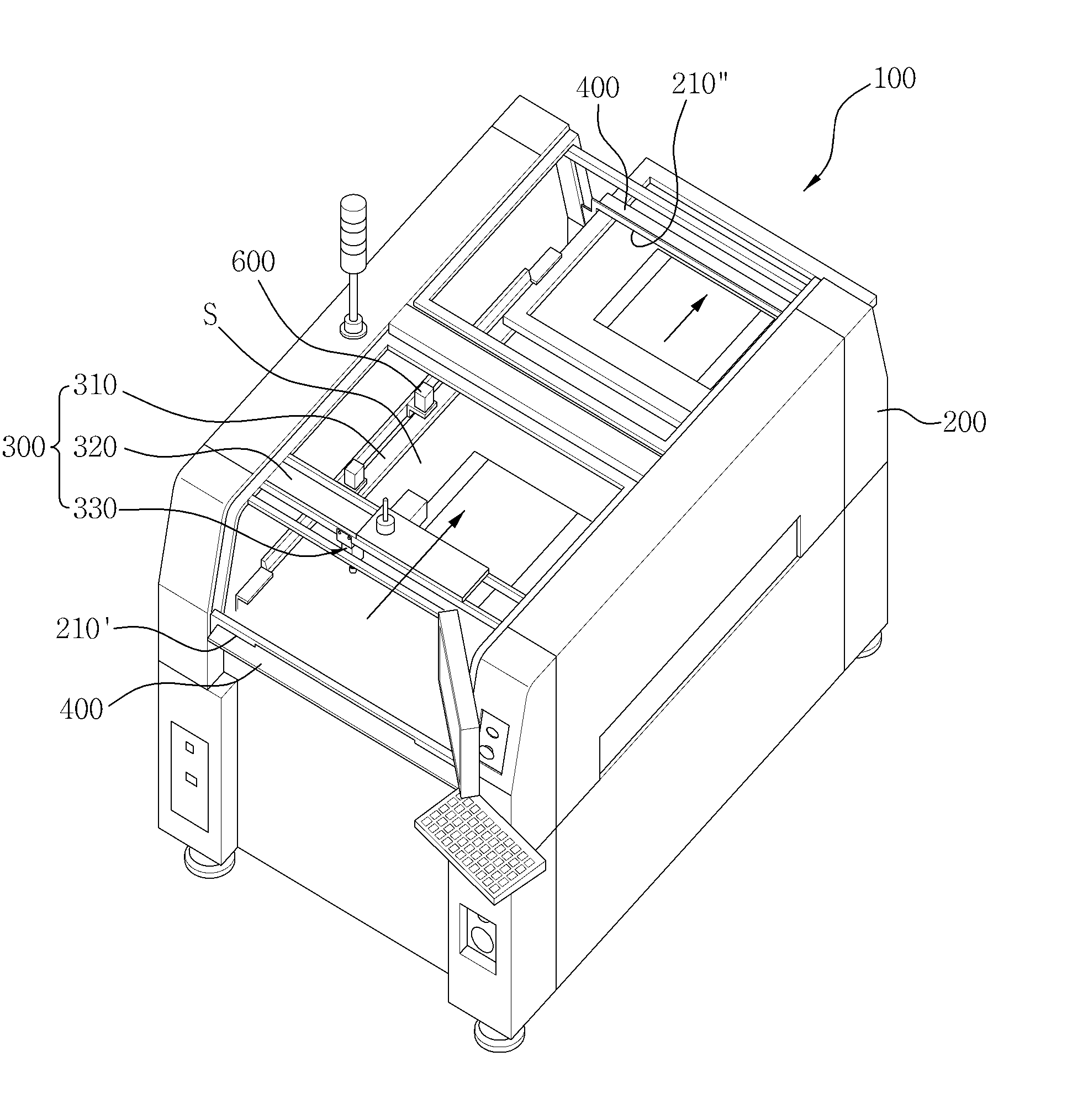
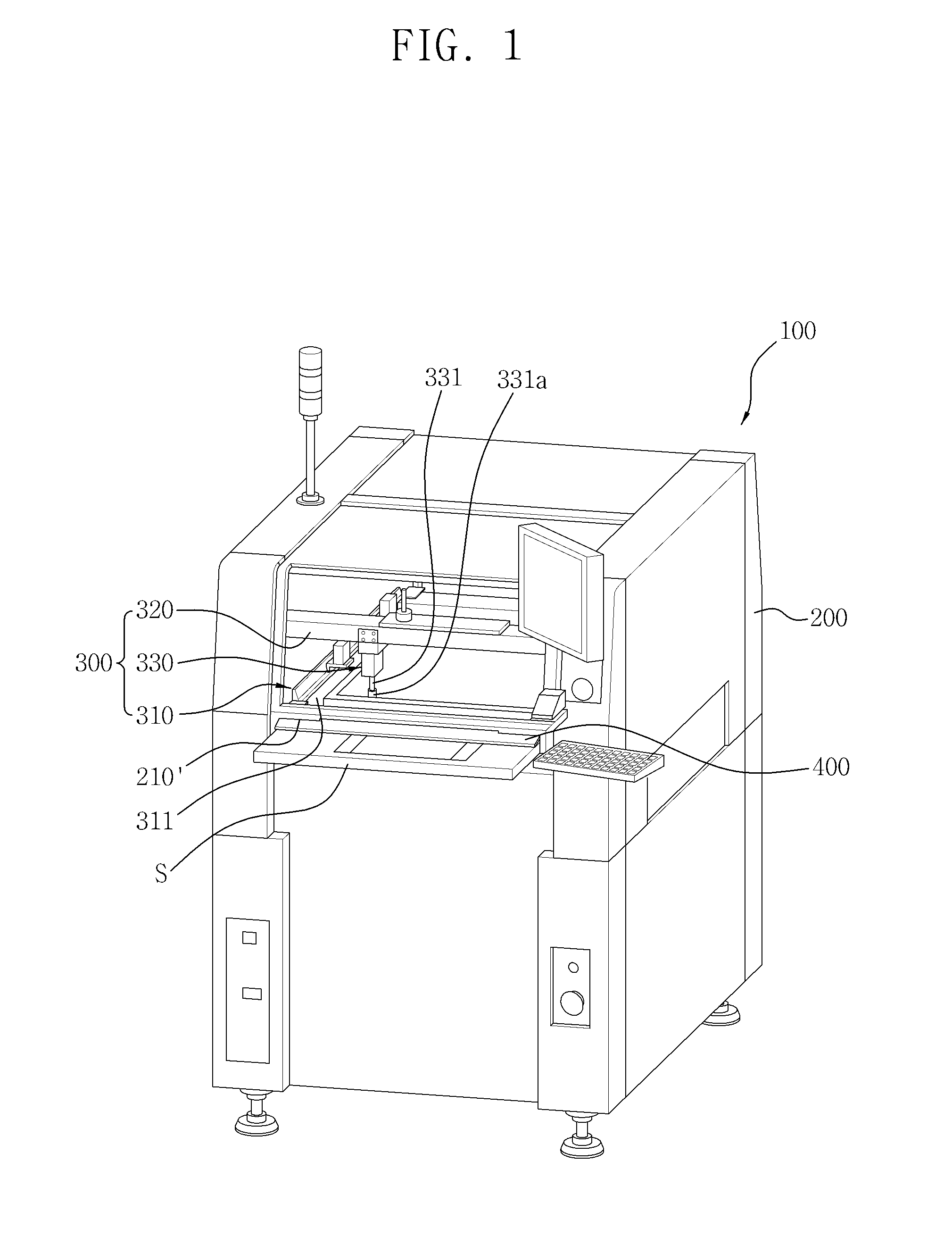
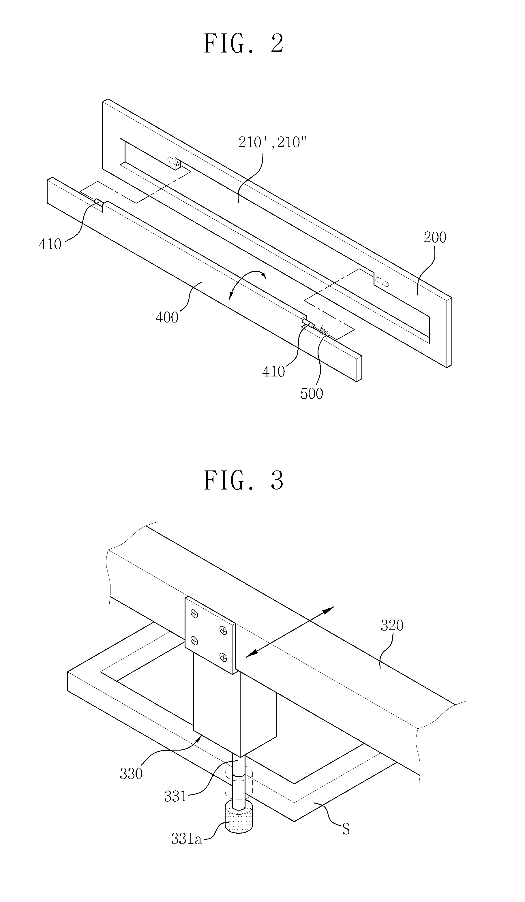
[0033]FIG. 1 is a perspective view showing a screen printer in accordance with an exemplary embodiment, FIG. 2 is an enlarged perspective view of an introduction and extraction portion and a blocking member of the screen printer in accordance with an exemplary embodiment, FIG. 3 is an enlarged perspective view of a slide part and a conveyance cylinder of the screen printer in accordance with an exemplary embodiment, FIGS. 4A to 4C show operation states of the screen printer in accordance with an exemplary embodiment, and FIGS....


PUM


Abstract

Provided is a screen printer including a main body in which an operation region and at least one introduction and extraction portion are formed, wherein the operation region includes an installation position of a stencil mask therein, and, through the at least one introduction and extraction portion, the stencil mask is introduced into the operation region and is extracted from the operation region to an outside of the main body; and a conveyance unit which conveys the stencil mask introduced into and disposed at the operation region to the at least one introduction and extraction portion when the stencil mask is replaced by a new stencil mask introduced through the at least one introduction and extraction portion, and conveys the new stencil mask to the operation region.

Description

CROSS-REFERENCE TO RELATED APPLICATION[0001]This application claims priority from Korean Patent Application No. 10-2010-0011951 filed Feb. 9, 2010 and Korean Patent Application No. 10-2011-0004941 filed Jan. 18, 2011, the disclosures of which are hereby incorporated herein by reference in their entirety.BACKGROUND[0002]1. Field[0003]Apparatuses consistent with exemplary embodiments relate to a screen printer, and more particularly, to a screen printer capable of easily exchanging a stencil mask with a new one, by forming introduction and extraction portions for a stencil mask without having to manually open / close a cover.[0004]2. Description of the Related Art[0005]In general, a screen printer is an apparatus for applying a cream solder-type lead solution to install parts such as an integrated circuit (IC), a resistor, and so on, in a plurality of contact spaces formed on a surface of a printed circuit board (PCB).[0006]A related-art screen printer includes a conveyor installed in a...

Claims


Application Information

Patent Timeline
IPC IPC(8): B05C17/08
CPCH05K3/1225
Inventor KIM, DONG-JOON
Owner HANWHA AEROSPACE CO LTD
Learn More