Method of forming an optical fiber buffer tube

a buffer tube and optical fiber technology, applied in the field of optical fiber cable construction, can solve the problems of ineconomic feasibility, shrinkage of the buffer tube, and increase of the excess fiber length (efl), and achieve the effect of less radial control

Inactive Publication Date: 2011-08-11
DRAKA COMTEQ BV
View PDF7 Cites 34 Cited by
  • Summary
  • Abstract
  • Description
  • Claims
  • Application Information

AI Technical Summary

Benefits of technology

[0008]In a further embodiment, the cured molten material surrounding the tube has a wall thickness less than the thickness of the tape, such that the dominant portion of the buffer tube wall thickness is made up of the pre-shrunk material to resist shrinkage of the buffer tube during curing and subsequent thereto. The cured molten material preferably makes up about 50% or less of the total buffer tube wall thickness, more preferably about 25% or less of the total buffer tube wall thickness, and even more preferably about 10% or less of the total buffer tube wall thickness. In the preferred embodiment, the cured molten material surrounds the outer surface of the formed tube and has a generally uniform wall thickness to provide a circular buffer tube cross-section. In an alternative embodiment, the formed tube may be internally coated to maintain and close the tube. Suitable materials for the pre-shrunk tape and molten material include, but are not limited to, polyethylene, polypropylene, polybutylene terephthalate, and polyethylene terephthalate.
[0009]In a further embodiment, the at least one optical fiber is loosely encased within the formed tube within a water blocking agent, such as a soft, thixotropic filling material. The at least one optical fiber may include a plurality of individual optical fibers or fibers arranged in a ribbon matrix. Additional elements including compressive and tensile strength members known to those skilled in the art may be included in the cable construction. In a further embodiment, the molten material may include a colorant for color-coding the buffer tube.
[0010]In a further embodiment, an extrusion vacuum calibrator is provided including a plurality of linearly-arranged, spaced apart calibrating disks, each of the disks including a hole defined therethrough having a diameter about equal to, or slightly larger, than the outer diameter of the tube subsequent to coating to control the outer diameter of the coated tube during cooling by restraining the coated tube against outward radial expansion. The disks may be more closely spaced apart proximate the entry side of the calibrator, where greater control of the outer diameter of the coated tube is required to maintain the shape, and spaced further apart from one another proximate the exit side of the calibrator, where less radial control is required. The calibrator may further include a water trough directing cooling water to the buffer tube for cooling the molten material and passing the buffer tube therethrough under vacuum.

Problems solved by technology

This can later lead to post-extrusion shrinkage if the buffer tubes are heated and allowed to reorient to a preferred non-oriented state, causing post-extrusion shrinkage in the buffer tube and a resultant increase in excess fiber length (EFL).
While technically feasible, this solution is not economically feasible.

Method used


Image

  • Method of forming an optical fiber buffer tube
  • Method of forming an optical fiber buffer tube
  • Method of forming an optical fiber buffer tube

Examples


Embodiment Construction

[0019]The present invention will now be described more fully hereinafter with reference to the accompanying drawings in which exemplary embodiments of the invention are shown. However, the invention may be embodied in many different forms and should not be construed as limited to the representative embodiments set forth herein. The exemplary embodiments are provided so that this disclosure will be both thorough and complete, and will fully convey the scope of the invention and enable one of ordinary skill in the art to make, use and practice the invention.

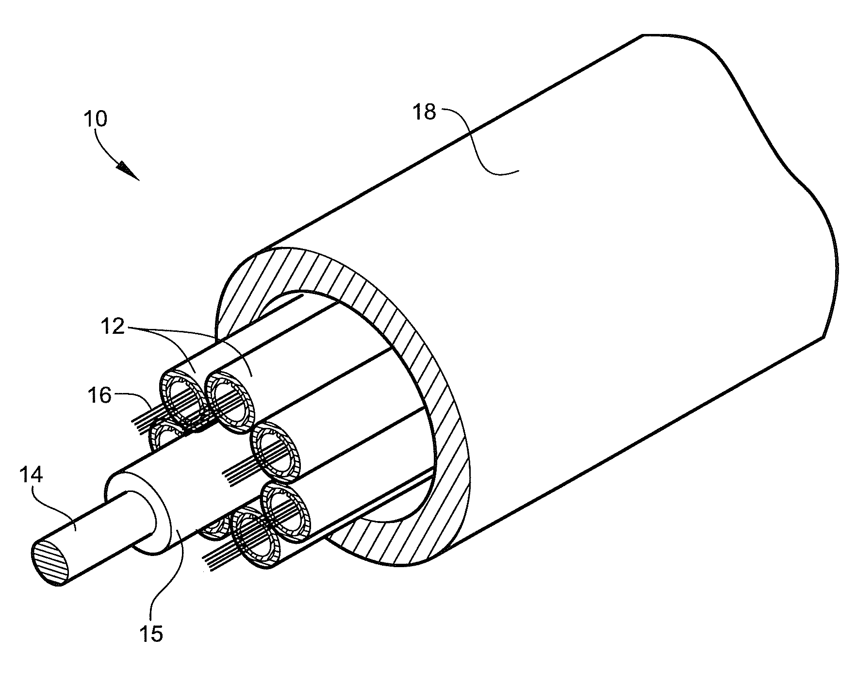
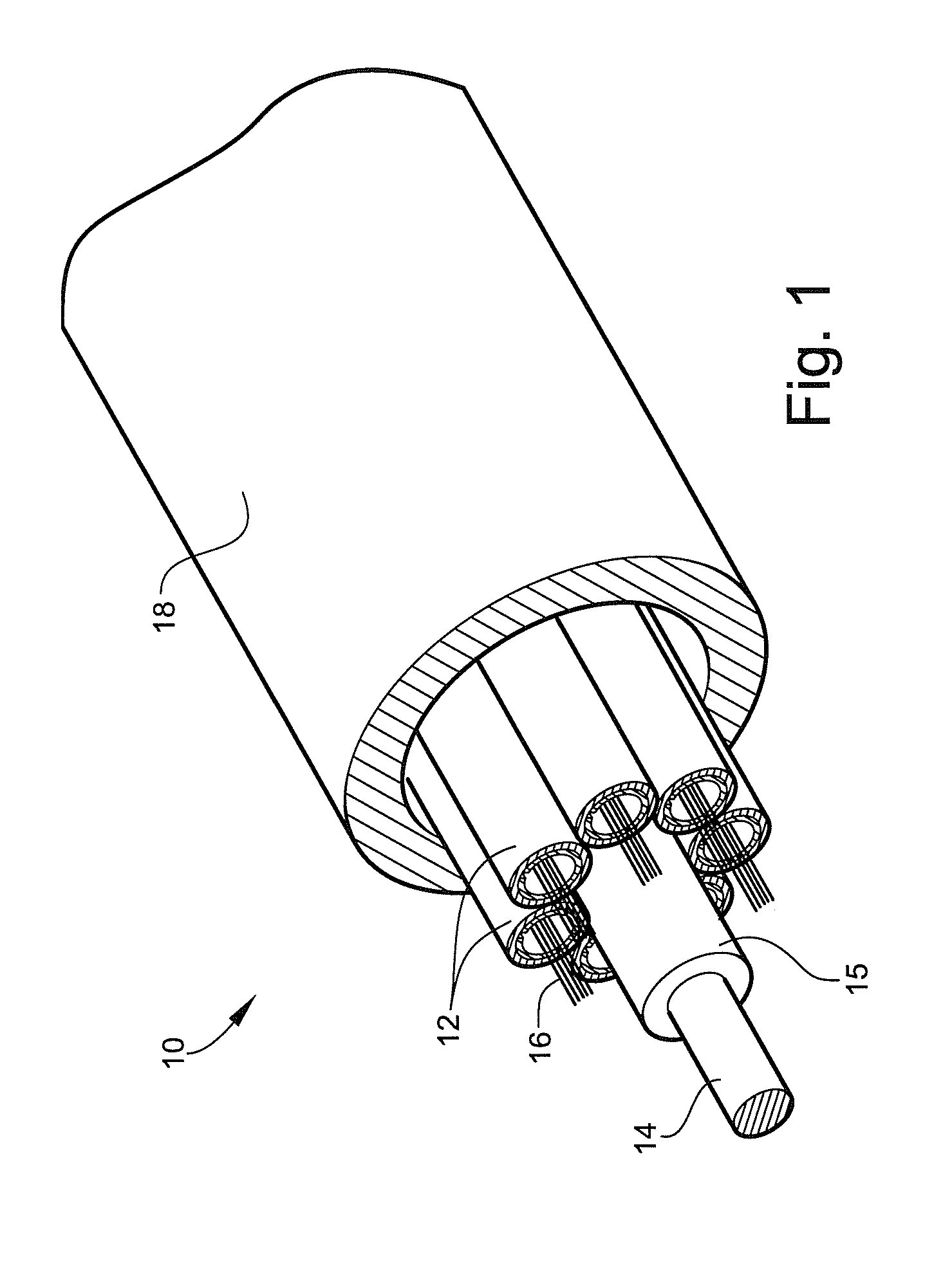
[0020]Referring to FIG. 1, a non-limiting example of a portion of an optical fiber cable including a buffer tube processed according to a method disclosed herein is illustrated generally at reference numeral 10. The cable 10 includes a plurality of buffer tubes 12 axially stranded about a central strength member 14, separated therefrom by a coating 15 that buffers contact between the buffer tubes 12 and the central strength member ...


PUM

PropertyMeasurementUnit
outer diameteraaaaaaaaaa
lengthaaaaaaaaaa
lengthaaaaaaaaaa

Abstract

A method of forming an optical fiber buffer tube including the steps of providing a length of pre-shrunk tape having a predetermined width and thickness, forming the tape into a tube around at least one optical fiber, coating the formed tube with a molten material to close the tube, and cooling the molten material to maintain the shape of the tube. The method further includes calibrating the outer diameter of the coated tube during the cooling step by restraining the coated tube against outward radial expansion. An optical fiber buffer tube constructed according to the method is further provided.

Description

TECHNICAL FIELD AND BACKGROUND OF THE INVENTION[0001]1. Field of the Invention[0002]The present invention relates generally to the field of optical fiber cable construction, and more particularly, to a method of forming an optical fiber buffer tube including forming a pre-shrunk tape into a tube around at least one optical fiber, coating the tape with a layer of molten material to surround the tube, and cooling the molten material to close and maintain the shape of the tube.[0003]2. Background of the Invention[0004]Certain types of loose tube optical fiber cables include a plurality of optical fibers, arranged either individually or in a ribbon matrix, loosely disposed within a buffer tube. Known to those skilled in the art, a buffer tube is the primary structure for protecting the optical fibers residing therein, and is typically made from materials having a high Young's modulus to provide tensile and compressive resistance against such loads.[0005]Conventionally, buffer tubes are ...

Claims


Application Information

Patent Timeline
Patent Type & Authority Applications(United States)
IPC IPC(8): G02B6/44B65H81/06
CPCG02B6/441G02B6/4486G02B6/4434
Inventor PARRIS, DONALD RAY
Owner DRAKA COMTEQ BV
Why Eureka
Try Eureka