

High-pressure forming method in tubular member for lowering forming pressure
An internal high-pressure forming and forming pressure technology, applied in forming tools, metal processing equipment, manufacturing tools, etc., can solve problems such as low product quality, cracking, and large forming pressure.
- Summary
- Abstract
- Description
- Claims
- Application Information
AI Technical Summary
Problems solved by technology
Method used
Image

Examples
specific Embodiment approach 1
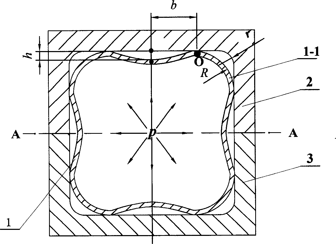
[0005] Specific implementation mode one: the following combination figure 1 This embodiment will be specifically described. The technical solution of this embodiment is achieved through the following steps: 1. Preform the pipe fitting 1 to be formed so that the cross section of the pipe fitting 1 becomes a "multi-petal flower shape", and the number and orientation of the petals 1-1 of the pipe fitting 1 are the same The number of rounded corners required to be formed on the top corresponds to the orientation; 2. Place the pipe fitting 1 to be formed into the cavity of the lower mold 3; 3. The upper mold 2 and the lower mold 3 are molded, and the pipe fitting 1 is in the upper mold 2 and the lower mold 3 in the cavity; 4. Introduce high-pressure liquid into the inner cavity of the pipe fitting 1 so that the pipe fitting 1 undergoes plastic deformation of outward expansion and is attached to the upper mold 2 and the lower mold 3. On the inner wall of the cavity; such as figure...
specific Embodiment approach 2
[0006] Specific implementation mode two: the following combination figure 1 This embodiment will be specifically described. The difference between this embodiment and the first embodiment is that the parting position A-A of the upper mold 2 and the lower mold 3 is on the straight side of the section of the cavity formed by the upper mold 2 and the lower mold 3 . Other steps are the same as those in Embodiment 1. The pipe fitting 1 to be formed in this embodiment needs to use separate preforming equipment and preforming molds to obtain the "multi-petal flower shape", or it needs to be obtained by cutting a profile with a prescribed shape.
specific Embodiment approach 3
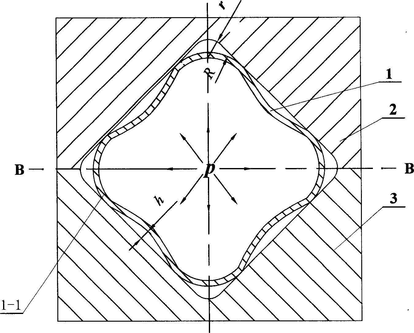
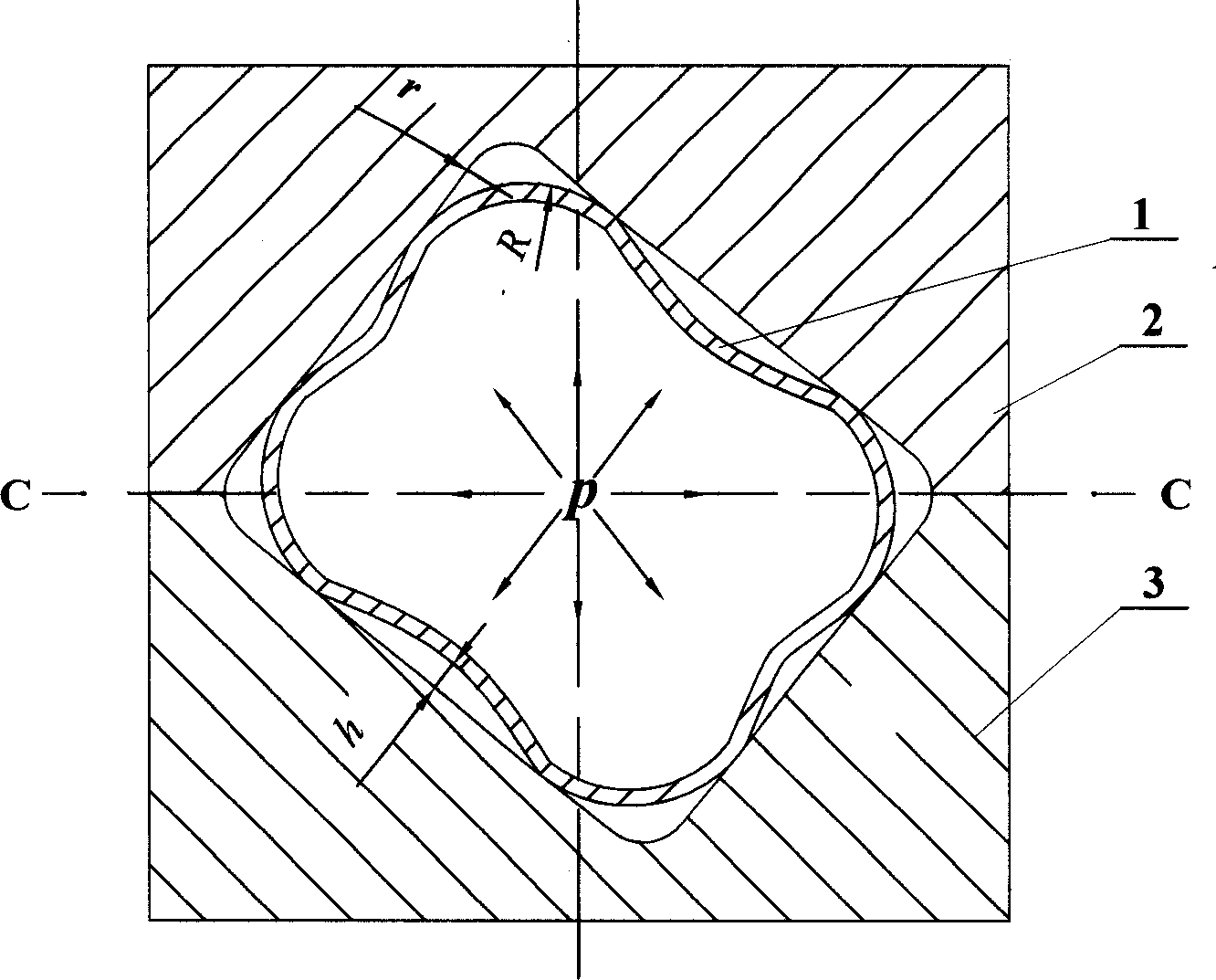
[0007] Specific implementation mode three: the following combination figure 2 This embodiment will be specifically described. The difference between this embodiment and the second embodiment is that the parting position B-B of the upper mold 2 and the lower mold 3 is at the fillet of the cavity section formed by the upper mold 2 and the lower mold 3 . Other steps are the same as the second embodiment. This embodiment adopts a common circular cross-section pipe fitting 1, and the pipe fitting 1 is placed in the upper mold 2 and the lower mold 3 that are parted at B-B. The distance between the opposite sides in the cavity is smaller than the diameter of the pipe fitting 1, and the upper mold 2 and the lower die 3 to pinch the pipe fitting 1, and deform the circular cross-section pipe fitting 1 into a pipe fitting 1 with a multi-petal flower-shaped cross-section. In this embodiment, the pre-forming and final forming of the pipe fitting 1 are completed in a set of molds, and no ...
PUM
 Abstract
Description
Claims
Application Information