Prescription drug lock box

Active Publication Date: 2015-02-03
SMALL STEVEN DOUGLAS
View PDF29 Cites 25 Cited by
  • Summary
  • Abstract
  • Description
  • Claims
  • Application Information

AI Technical Summary

Benefits of technology

[0008]It is the object of the present invention to provide a prescription drug lock box that has the following advantages which are:
[0009]Still further objects and advantages will become apparent from a consideration of the ensuing description and drawings.
[0010]This invention pertains to a prescription drug lock box consisting of a container and a detachable combination locking cover assembly used to secure the contents held within. The container has an integrally formed key post positioned above its open end. The tumblers of the cover assembly engage the key post and lock to it thus securing contents held within. When the indicia of the tumblers and correct unlocking code are in alignment with a marker, the cover assembly may be installed or removed.
[0011]The container is a hollow part with uniform wall thickness having a flat horizontal bottom wall, a continuous vertical side wall, and open at the top. In the preferred embodiment, a curved bar with two legs is joined to opposing sides of the container's interior. The bar legs extend vertically from the side wall of the container, curve towards each other, and form a horizontal portion which is centered to the container and above the open end. The bar thus forms a closed rigid arch above the container's open end. From the center of the arch, an integrally formed cylindrical post extends further vertically. Projecting outwardly on the post's side wall is a linear array of tabs. The tab array is oriented in longitudinal direction from the top of the post. The tabs and post together represent a “key post” feature. The cover assembly and tumblers engage and lock to the key post. There are many methods for integrating and positioning a key post above the open container. For instance, in one alternate way, the key post could be formed on top of an integrally formed vertical column that projects upwardly from the center of the containers bottom wall. The presence of a central column would however take up some available space in the container. The bars and key post can be integrally molded or formed directly as features of the container where container, bars, and key post are injection molded or die cast as one single part. For ease of manufacture, and simpler injection molding, the preferred embodiment of this application shows the bars and post as being a separate rigid part that is bonded into a seat provided in the container. In another design variation, the bar could potentially attach to the container with a pivot on either side. With the bar able to swivel and rotate, the horizontal bar portion and key post could pivot out of the way with less obstruction to the container's opening.
[0012]The combination locking cover assembly consists of a cover, a set of locking tumblers, and a retaining cap. The cover is a hollow part with uniform wall thickness, having a continuous vertically oriented side wall, an upper wall, and fully open at the bottom end. Shape and cross-sectional profile of the cover's side wall concentrically matches and fits over the container's side wall. The cover and container nest and fit together, where the cover side wall overlaps and is outside of the container's side wall. In this manner the cover sheaths and closes off the container. The general form factor or horizontal cross-sectional profile of container and cover's side walls could be cylindrical, elliptical, rectangular, or of any shape. Illustrations of this application show the cross-sectional form factor as being elliptical. The shape and size of the cover provides clearance with the arched bar feature of the container when the device is fully assembled. A short protrusion extends vertically above the upper wall of the cover and creates a “tumbler seat” which is used to support the stack of tumblers. Projecting upwardly from the tumbler seat is a cylindrical shaft portion with a closed top end. A vertical key slot cuts through the tumbler seat and partially through shaft side wall. The cover's key slot provides clearance with the tabs of the key post and permits assembly and disassembly. A D-shaped profile counterbore is reces

Problems solved by technology

The presence of a central column would however

Method used


Image

  • Prescription drug lock box
  • Prescription drug lock box
  • Prescription drug lock box

Examples


Embodiment Construction

FIGS. 1-A Through 7-D, Preferred Embodiment

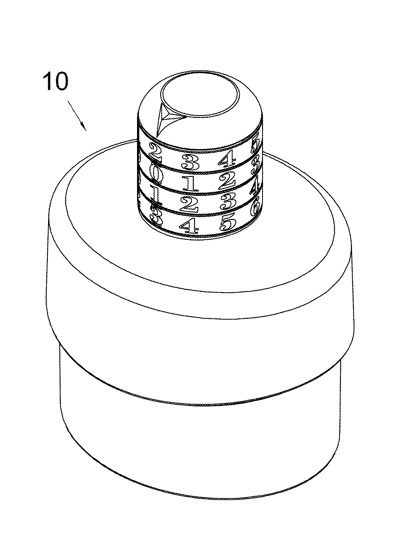
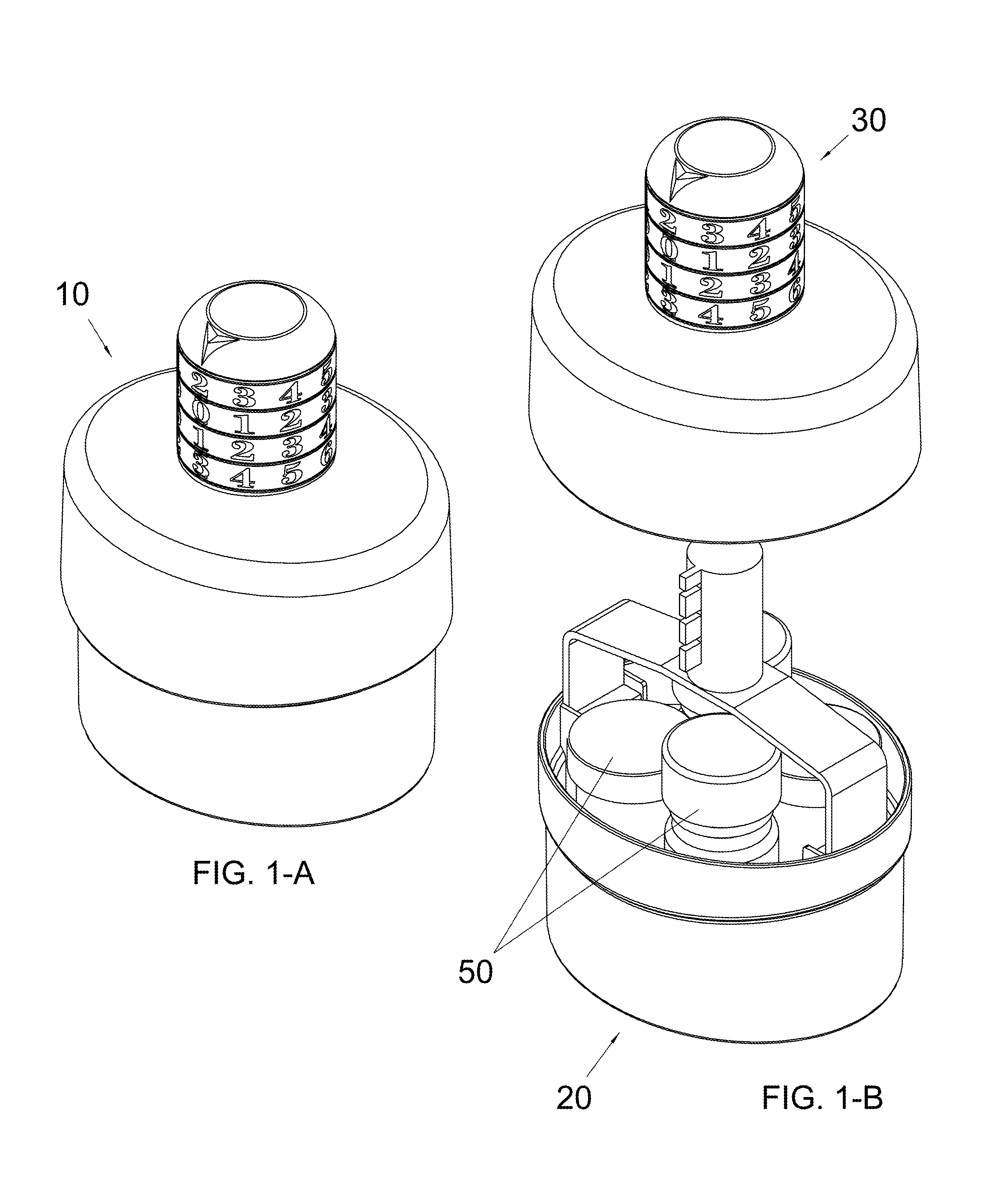
[0039]A preferred embodiment of the container of the present invention is illustrated in FIGS. 1-A through 7-C. The present invention provides a prescription drug lock box 10 shown generally in FIG. 1-A. FIG. 1-B shows an exploded view of the device consisting of a container 20, and a combination locking cover assembly 30. The container can hold any number of items including, but not limited to, prescription drug bottles 50.

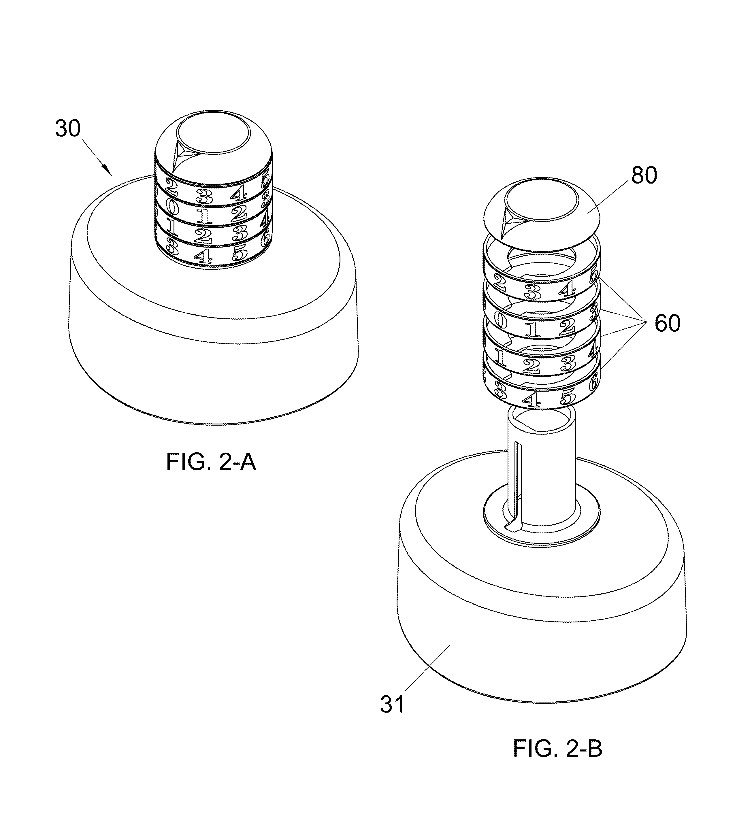
[0040]FIG. 2-A shows an oblique view of the cover assembly 30. FIG. 2-B shows an exploded view of the cover assembly consisting of cover part 31, a set of locking tumblers 60, and a retaining cap 80.

[0041]FIG. 3-A shows an oblique view of the cover part 31 from above. FIG. 3-B shows an oblique view of the cover part from beneath. FIG. 3-C shows a cross-sectional view of the cover. The cover is generally a hollow thin walled part of uniform wall thickness, having interior and exterior surfaces, a vertically oriented side ...


PUM


Abstract

This invention pertains to a prescription drug lock box consisting of a container and a detachable combination locking cover assembly used to secure the contents held within. The container has an integrally formed key post positioned above its open end. The tumblers of the cover assembly engage the key post and lock to it thus securing contents held within. When the indicia of the tumblers and correct unlocking code are in alignment with a marker, the cover assembly may be installed or removed.

Description

CROSS-REFERENCE TO RELATED APPLICATIONS[0001]This application claims the benefit of PPA Ser. No. U.S. 61 / 765,651, filed 2013 Feb. 15 by the present inventor.FEDERALLY SPONSORED RESEARCH[0002]NoneSEQUENCE LISTING[0003]NoneTECHNICAL FIELD[0004]This invention relates to storage containers. In particular this disclosure relates to a prescription drug lock box that utilizes a detachable combination locking cover assembly that can secure a container and the contents held within.BACKGROUND OF THE INVENTION[0005]This invention relates to a prescription drug lock box which can be used for securing various items including but not limited to pharmaceuticals, hospital and office supplies, chemicals, household cleaning products, personal electronics, cell phones, jewelry, personal items and the like.[0006]Its most significant application might be for better securing prescription drugs within the home. Misuse of pharmaceutical drugs is a significant problem in today's society. Drugs can often be ...

Claims


Application Information

Patent Timeline
IPC IPC(8): A61J1/00B65D55/02E05B37/02E05B65/00E05B73/00
CPCE05B65/0014E05B37/02E05B73/00B65D55/145Y10T70/5009Y10T70/5575
Inventor SMALL, STEVEN DOUGLAS
Owner SMALL STEVEN DOUGLAS
Why Eureka
Try Eureka