Clamp for male terminal

Inactive Publication Date: 2011-08-11
MTA SPA
View PDF7 Cites 16 Cited by
  • Summary
  • Abstract
  • Description
  • Claims
  • Application Information

AI Technical Summary

Benefits of technology

[0009]The object of the present invention is therefore to propose a clamp for r ale terminal

Problems solved by technology

However, this clamping system causes the flanges to twist

Method used


Image

  • Clamp for male terminal
  • Clamp for male terminal
  • Clamp for male terminal

Examples


first embodiment

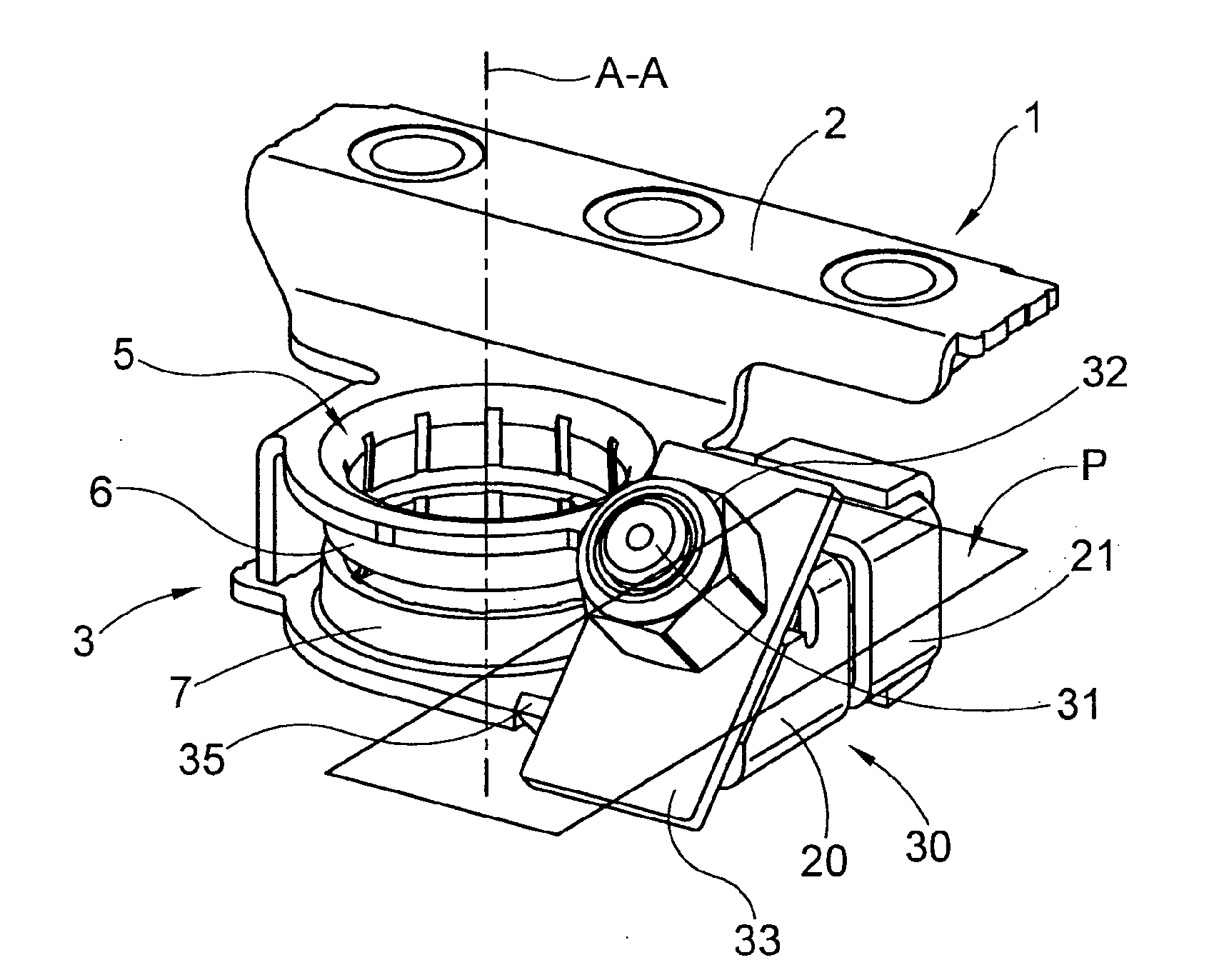
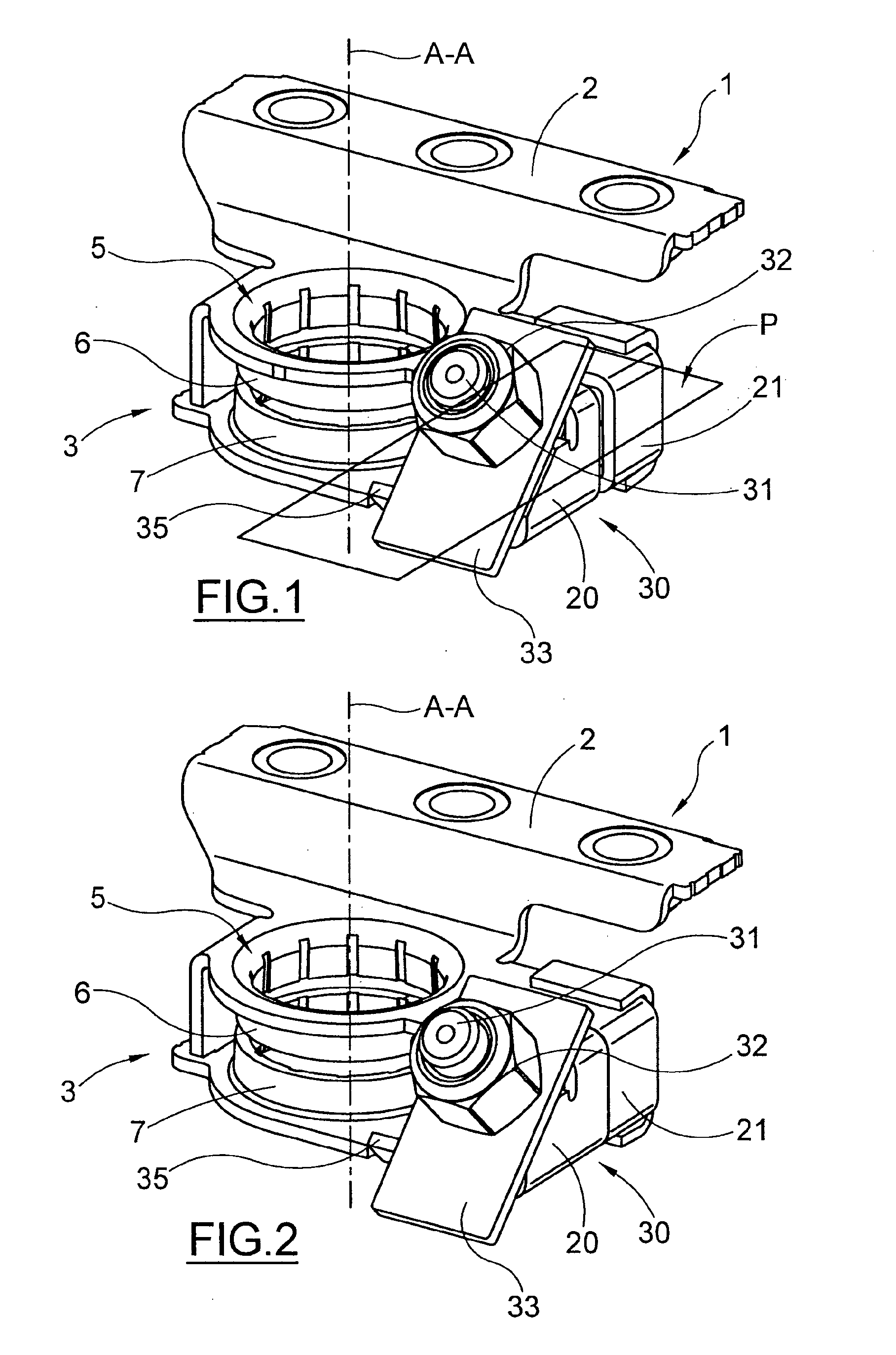
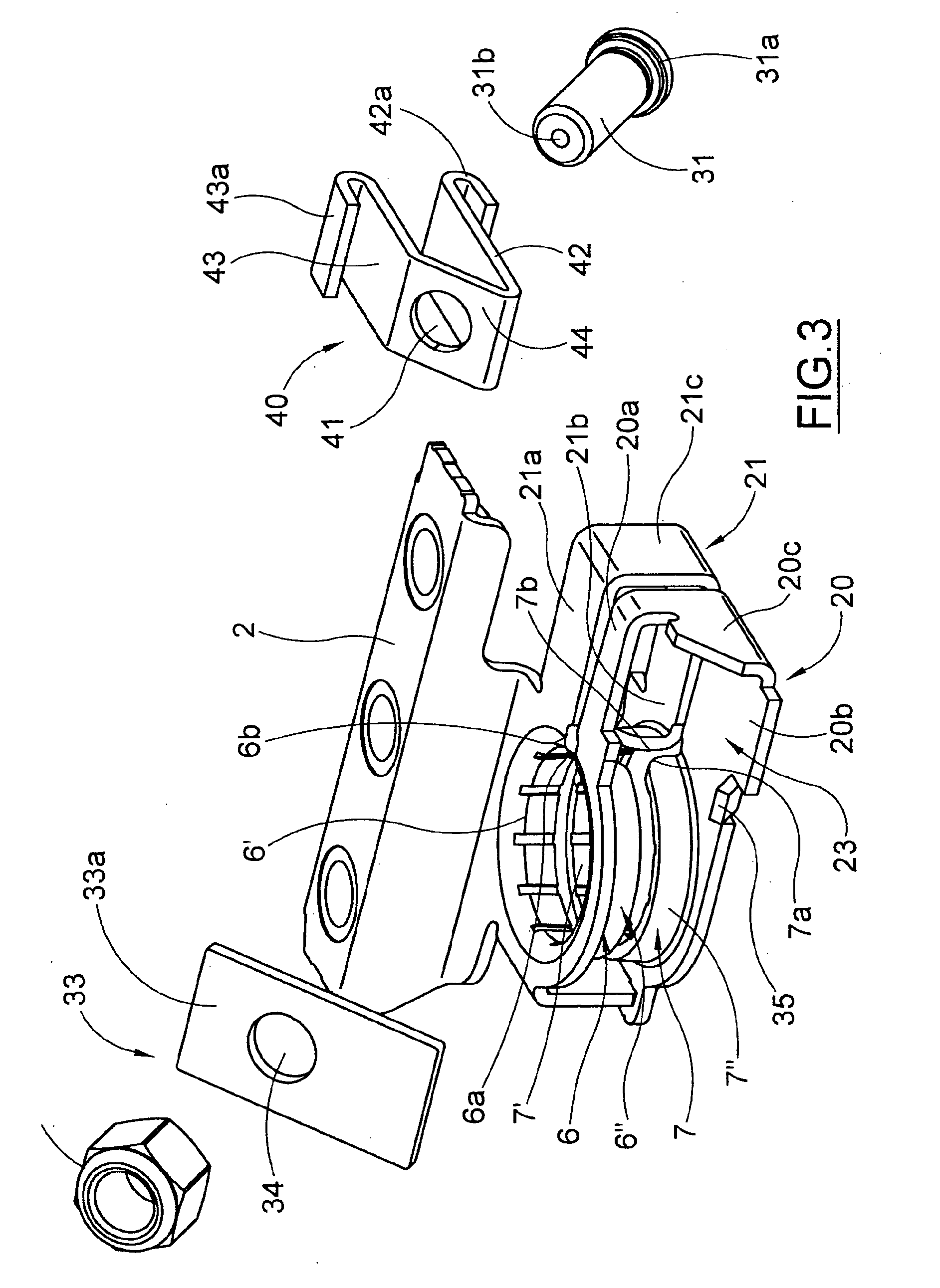
[0069] shown in FIGS. 1 to 11, the clamping means 30 comprise a clamping screw 31 extended along the clamping axis B-B, secured, at one end 31a, to the guiding means 40 and having an opposite free end 31b. In order to simplify the overall representation of the clamp, the clamping screw shown in the annexed figures is schematized without thread. However, it is understood that this clamping screw has a thread (not shown in the figures).

[0070]The slider 40 has an opening 41 for securing the end 31a of the clamping screw 31. The securing of the clamping screw 31 to the slider 40 can be carried out by inserting the base 31a of the clamping screw 31 by interference into the hole 41. Alternatively, other means for securing the clamping screw 31 to the slider 40 can be used.

[0071]The rotatable clamping member is made of a clamping nut 32 mounted as rotating on the clamping screw 31 on the side of the free end 31b and it engages the clamping plate 33 to move the jaws 20, 21 between the close...

third embodiment

[0082] shown in FIGS. 23 to 33, showing a clamp 201, the rotatable clamping member of the clamping means 230 comprises a clamping screw 231 having a portion 232 to drive in rotation such screw 231 and capable of engaging the clamping plate 33, and an end portion 233 engaged with the guiding means 240.

[0083]In this case, the slider 240 comprises a body extending along the direction X-X and having a trapezium rectangular section. In particular, the slider comprises two upper 242 and lower 243 walls parallel to each other, one inclined wall 244 connecting the two walls 242, 243 and a bottom wail 245 engaging the fixed jaw 21. The inclined wall 244 lies on a plane perpendicular to the clamping axis B-B and therefore parallel to the plane on which the surface 33a of the clamping plate 33 lies. On opposite side of the wall 244, the bottom wall 245 has hooking means 246 to allow the engaging of the slider 240 with the jaw 21. Namely, the hooking means 246 correspond to a flange projecting ...

sixth embodiment

[0094]In this sixth embodiment, since the clamping screw 31 moves on plane P along the direction X-X inside the slot 134, the clamping surface 33a can also correspond to a connecting wall between the upper wall 20a and the lower wall 20b of the jaw 20. In this case, the slot 134 is configured so as to allow the plate 133-clamping screw 31 relative movement of the clamping means 130 not only along the clamping axis B-B but also along the clamping direction X-X.


PUM


Abstract

A clamp for male terminal comprising a clamping ring capable of inserting on a male terminal, two jaws connected to the clamping ring and mutually approachable to tighten the clamping ring on the male terminal, clamping means acting on the jaws to move them between a distant position and a close position along a clamping direction. The clamping means comprise a clamping member rotating around a clamping axis inclined with respect to a plane perpendicular to the axis of the clamping ring. The clamp further comprises guiding means cooperating with a movable jaw to guide the movement of such movable jaw along the clamping direction on said plane, between the distant position and the close position.

Description

TECHNICAL FIELD[0001]The present invention relates to a clamp for a male terminal.[0002]In particular, the present invention relates to a clamp with inclined clamping screw.[0003]The clamp of the present invention can find application for the connection to a battery post. In this case, the male terminal is a battery post while the clamp is connected to one or more utilities of a motor vehicle.[0004]According to a different application, the clamp of the present invention can find application for the grounding of electric and / or electronic devices. In this case, the male terminal is a ground terminal secured to a structure serving as earth ground, while the ground connection of the devices to be grounded is connected to the clamp by electric cable. The structure serving as earth ground can be, for example, the body of a motor vehicle, in particular of a car.BACKGROUND OF THE INVENTION[0005]An inclined-clamping battery terminal clamp is disclosed for example in the Japanese publication...

Claims


Application Information

Patent Timeline
IPC IPC(8): H01R4/40H01R4/50
CPCH01R11/283H01R11/282
Inventor FALCHETTI, ANTONIO
Owner MTA SPA
Why Eureka
Try Eureka