Check patentability & draft patents in minutes with Patsnap Eureka AI!

Shoe sole with reinforcing structure

a technology of reinforcing structure and shoe sole, which is applied in the field of shoe sole with reinforcing structure, can solve the problems of weight saving, preventing distortion, and unable to solve the problems of art disclosed in each patent document at the same time, so as to reduce the weight of the shoe sole and prevent the effect of shoe sole distortion

Inactive Publication Date: 2011-08-18
ASICS CORP
View PDF51 Cites 22 Cited by
  • Summary
  • Abstract
  • Description
  • Claims
  • Application Information

AI Technical Summary

Benefits of technology

The design achieves a lightweight shoe sole that prevents distortion, enhances fitting properties, and reduces upthrust by allowing independent deformation of arches, thereby improving the overall performance and comfort.

Problems solved by technology

However, such a structure often creates a midsole arch that is too stiff for the wearer and which is hard to fit to the arch of the wearer's foot.
None of the aforedescribed art provides a shoe sole that is light in weight, prevents distortion, has improved fitting properties and prevents the described-upthrust.
That is, the art disclosed in each of the patent documents cannot solve simultaneously the problems of weight saving, prevention of the distortion, improvement in the fitting properties and prevention of the upthrust.

Method used


Image

  • Shoe sole with reinforcing structure
  • Shoe sole with reinforcing structure
  • Shoe sole with reinforcing structure

Examples


first embodiment

[0091]Hereinafter, a first embodiment of the invention will be described with reference to the drawings. In this first embodiment, the principle embodiment is shown and the basic structure and principle of this invention will be described.

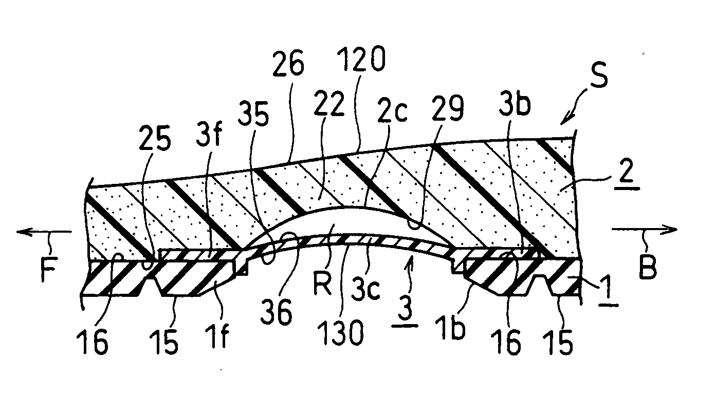
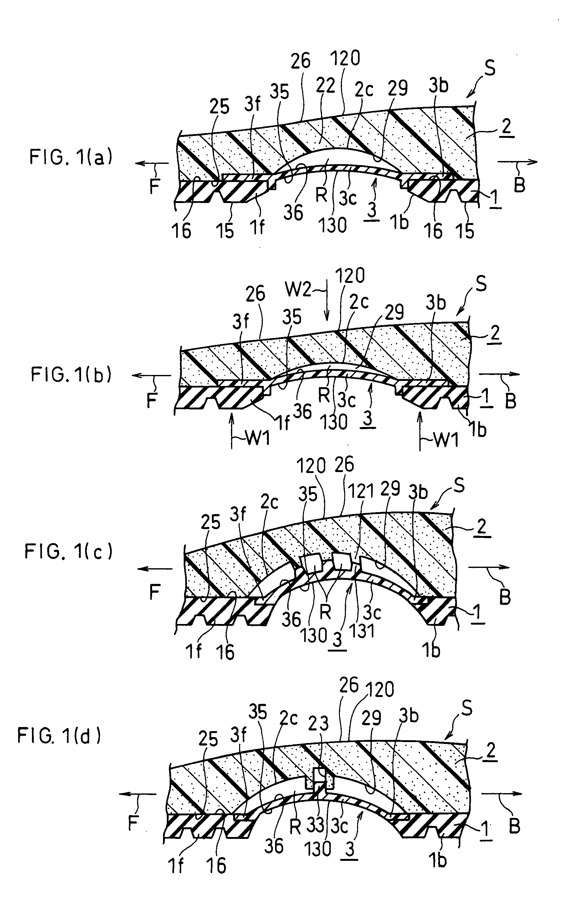
[0092]FIG. 1(a) and FIG. 1(b) are schematic sectional views of a shoe sole S in the middle foot part, i.e., arch region of the foot. The arrow F is the direction toward the front of the shoe and the arrow B is the direction toward the rear or back of the shoe.

[0093]As shown in FIG. 1(a), the shoe sole S comprises an outer sole 1, a midsole 2 and a reinforcing member 3 for reinforcing the midsole 2.

[0094]The outer sole 1 is divided at just under the arch of the foot into a fore foot part 1f and a rear foot part 1b. Each part 1f, 1b of the outer sole 1 has a ground contact surface 15 which has ground contact at the time of landing, and a top surface 16 opposite to the ground contact surface 15.

[0095]As shown in FIG. 1(a), the midsole has a top surfac...

second embodiment

[0109]Next, a second embodiment will be described with reference to FIG. 2, FIG. 3, FIG. 4 and FIG. 5. In the following description of embodiments, the parts which are identical or corresponding to those of the first embodiment are designated by the same reference numerals as the first embodiment and the detailed description and illustration thereof will be omitted.

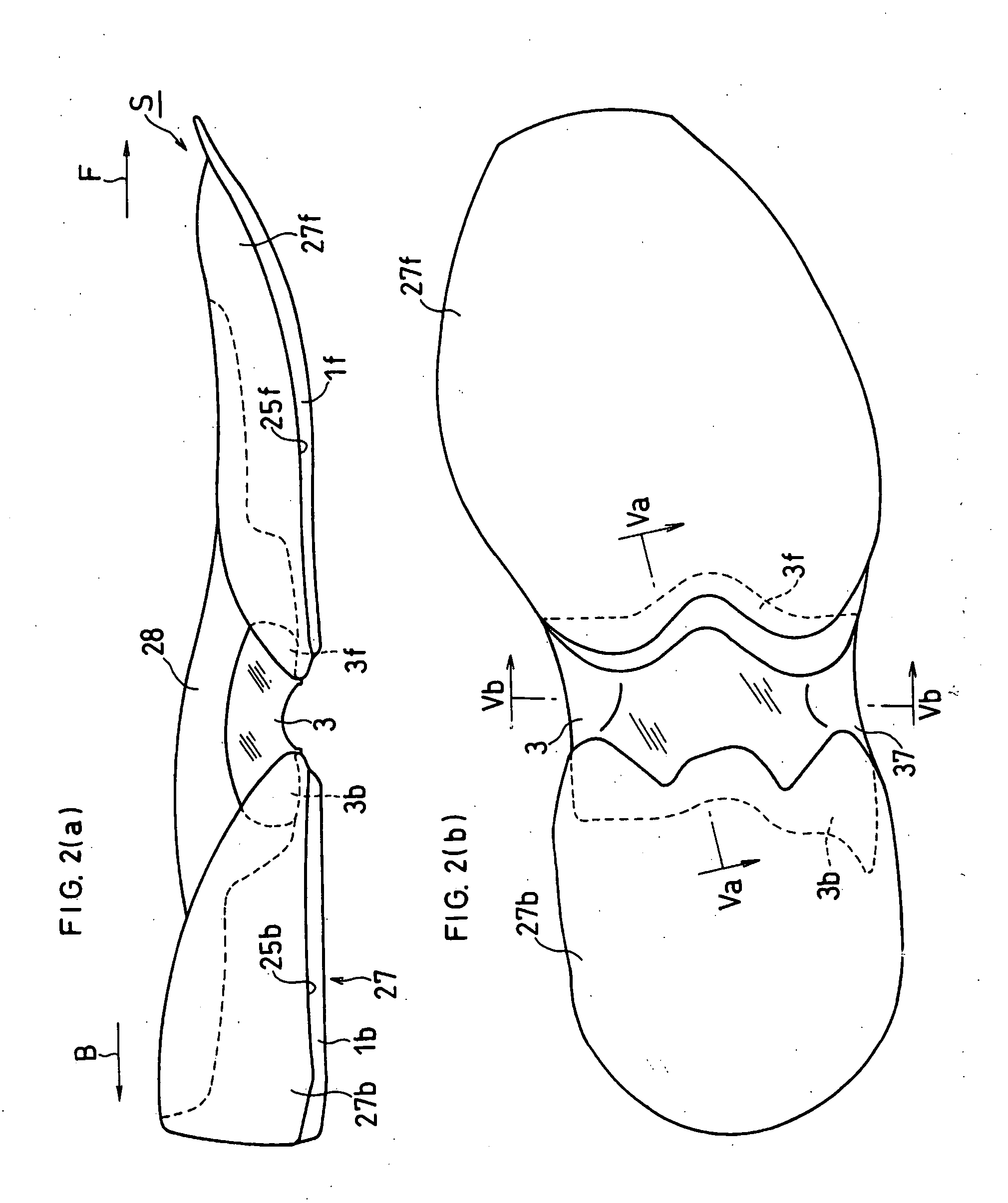
[0110]FIG. 2(a) is a side view showing the shoe sole S with an outer sole 1f, 1b attached. FIG. 2(b) is a bottom view showing the shoe sole S without the outer sole attached.

[0111]As shown in FIG. 2(a), the shoe sole S comprises an upper midsole body 28, a lower midsole body 27 and a reinforcing member 3. In this embodiment, the upper and lower midsole bodies 28, 27 constitute the midsole 2. The lower midsole body 27 is divided at the position corresponding to the arch of the foot into a front part 27f and a rear part 27b. The fore foot part 1f of the outer sole 1 is attached to the bottom surface 25f of the front part 27...

third embodiment

[0131]FIG. 6(a) is a longitudinal sectional view of a shoe sole according to a third embodiment.

[0132]As shown in FIG. 6(a), a first reinforcing member 39 and a second reinforcing member 40 are provided. The second reinforcing member 40 is a different member from the first reinforcing member 39. The second reinforcing member 40 is located below the first reinforcing member 39.

[0133]The first reinforcing member 39 corresponds to the reinforcing member 3 according to the above-mentioned first and second embodiments and has the second arch 3c. The second arch 3c is arranged to be opposite to the first arch 2c of the midsole 2 and to be vertically spaced from the first arch 2c.

[0134]On the other hand, the second reinforcing member 40 is for reinforcing the first reinforcing member 39. Such second reinforcing member 40 further prevents the distortion of the shoe sole at the arch of the foot.

[0135]In the example of FIG. 6(a), a fore end part 40f and a rear end part 40b of the second rein...


PUM


Abstract

This invention relates to a shoe sole that solves the problems on weight saving in shoes, prevention of distortion, improvement in the fitting property and prevention of upthrust simultaneously. The reinforcing member 3 for reinforcing a part of the midsole 2 is arranged so that the top surface 36 of the second arch 3c and the bottom surface 29 of the first arch 2c are opposite to each other. At least a part of the bottom surface 29 of the first arch is not in contact with a part of the top surface 36 of the second arch in vertically spaced relationship to each other, thereby that the non-contact areas of the first arch 2c and the second arch 3c can be deformed independently from each other when impact load of landing is applied.

Description

TECHNICAL FIELD[0001]The present invention relates to a shoe sole with a reinforcing structure having a so-called shank (reinforcing member).BACKGROUND ART[0002]A shoe sole that has a reinforcing member conforming to the shape of the arch of the midsole in the arch portion, for example, a shoe sole in which a portion of the midsole not attached to the outer sole does not have ground contact when the outer sole is grounded, is known. Such a reinforcing structure increases the rigidity of the arch portion of the midsole by suppressing deformation of the midsole. Examples of such known structures are shown in FIG. 9(a), FIG. 9(b), FIG. 10(a), FIG. 10(b) and FIG. 10(c).[0003]FIG. 9(a) is a side view of a shoe sole disclosed in Japanese Patent Laid Open No. 10-155511 (Abstract, therein) (publication date: Jun. 16, 1998). This shoe sole is provided with a supporting member 3 for supporting deformation of the arch of the foot on the top surface of a midsole 2. A space R is provided between...

Claims


Application Information

Patent Timeline
Patent Type & Authority Applications(United States)
IPC IPC(8): A43B13/18A43B13/12A43B13/42A43B13/14A43B13/16
CPCA43B3/0036A43B13/10A43B13/181A43B13/146A43B13/16A43B13/12
Inventor KUBO, SEIJIKUROSAKI, KIYOMITSUNISHIWAKI, TSUYOSHI
Owner ASICS CORP
Features
  • R&D
  • Intellectual Property
  • Life Sciences
  • Materials
  • Tech Scout
  • Unparalleled Data Quality
  • Higher Quality Content
  • 60% Fewer Hallucinations
Learn More