Pergola structure

a structure and pergola technology, applied in the direction of sunshade, flooring, building roofs, etc., can solve the problems of complex and time-consuming assembly, high risk of weather and rot, and classical and contemporary pergola structures

Active Publication Date: 2011-08-18
VINYL FENCES
View PDF4 Cites 13 Cited by
  • Summary
  • Abstract
  • Description
  • Claims
  • Application Information

AI Technical Summary

Problems solved by technology

Both classical and contemporary pergola structures, however, present a number of problems.
For example, although pergola structures are comprised of a limited number of types or different forms of elements, that is, upright posts, carrying rails and cross rails with a few decorative trim elements, a given pergola structure is comprised of a relatively large number of such elements, resulting in a complex and time consuming assembly that typically must be constructed by an experienced worker in order to obtain a relatively strong structure.
That is, and for example, the upright posts are rarely provided with any form of bracing, except by the carrying rails at their top, the cross rails are only weakly secured to the carrying rails and contribute little to the to the strength of the structure, and a pergola structure contains many joints, all of which are exposed to the weather and stress and thereby comprise points of weakness.
These problems are compounded by the materials used to construct pergolas, which are classically constructed of wood, which is highly susceptible to weather and rot, particularly at the joints.
Such structures, however, while avoiding or alleviating at least certain of the effects of weather and exposure to the elements, typically have many of the problems presented by traditional materials and constructions methods, that is, assembly of painted wood parts.
That is, it is often difficult for relatively unskilled workers to assemble a satisfactory structure, and the materials used, in composition, dimensions and design, and the design of the structural elements and their assembly, often do not result in a satisfactory structure, even when assembled correctly, with the jointing of the component parts remaining a particular problem.

Method used


Image

  • Pergola structure
  • Pergola structure
  • Pergola structure

Examples


Embodiment Construction

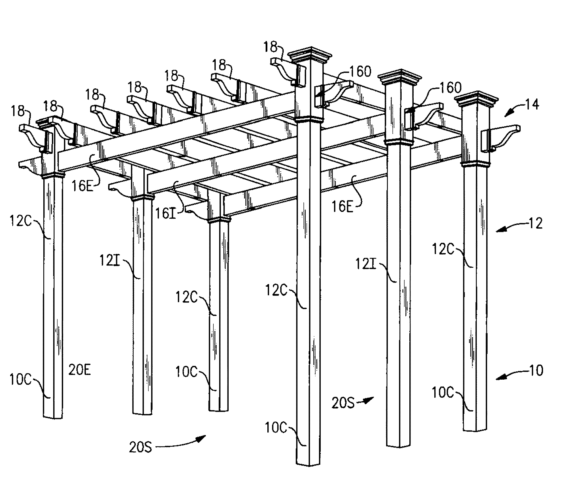
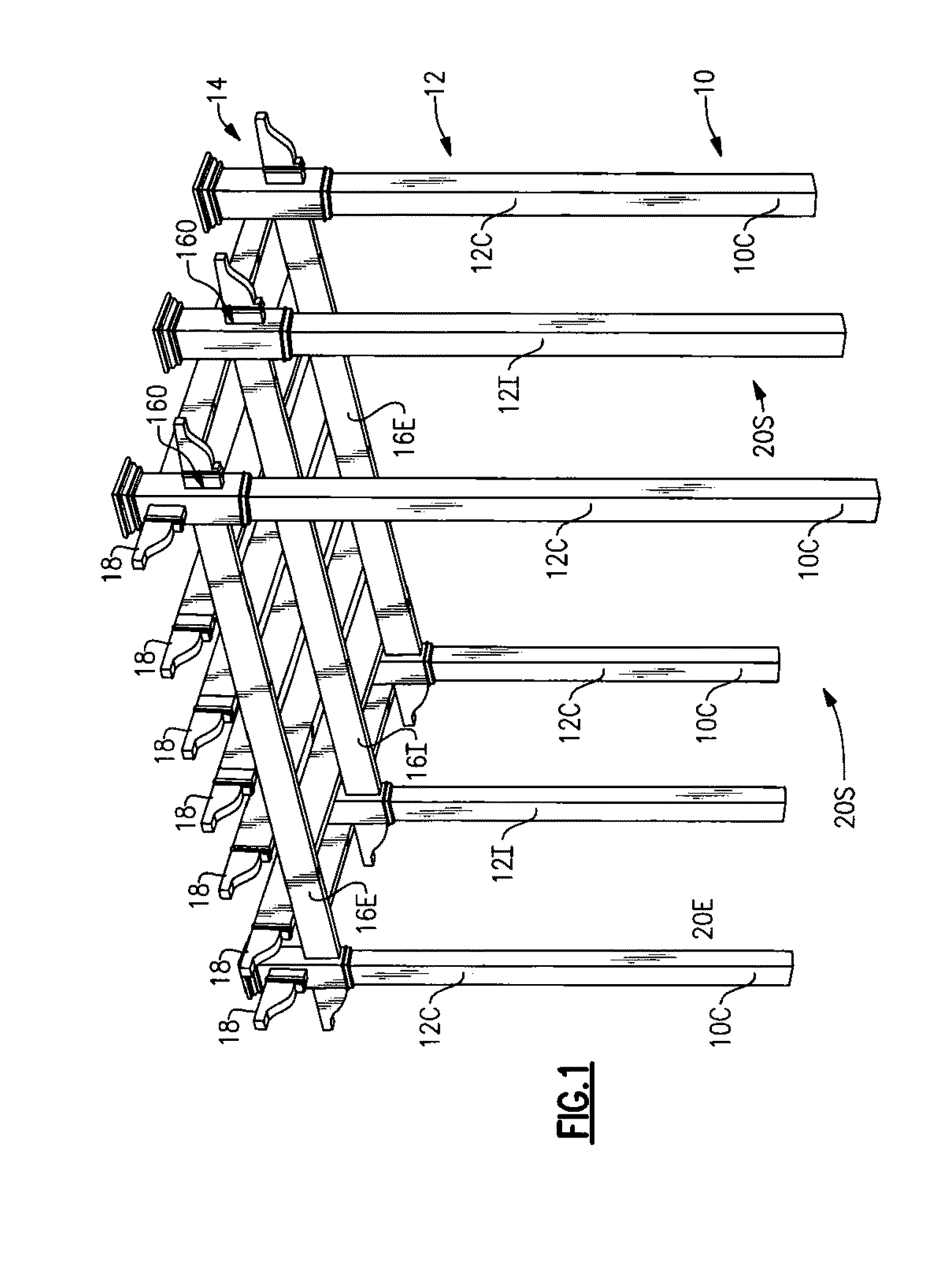
[0025]As described herein above and as illustrated in FIG. 1, a classic generally rectangular pergola type structure 10 includes a plurality of vertical posts 12 arranged around the periphery of an area that is covered by a roof 14 comprised of a rectangular grid or lattice of roof rails 16, 18 supported by the upright posts 12. For purposes of the following description and discussions, a pergola structure may be considered to have two ends 20E comprised of opposing sides of the rectangular area and two sides 20S comprised of the remaining opposing sides of the structure, which are orthogonal to the ends 20E of the structure 10.

[0026]It will be recognized, however, that a pergola structure 10 may assume configurations other than the simple rectangular or square form, such as two or more mating rectangles or squares, a walkway or a multi-angular plan, with appropriate adaptations in the details of the post and rail assemblies. In addition, one or more sides or ends of a pergola struc...


PUM


Abstract

A system of structural elements for a pergola structure including vertical posts supporting a roof formed of carrying rails supported by the posts and cross rails supported by the carrying rails. Each post includes a post core element, a post shell enclosing the post core element, and a post shell adapter. Each carrying rail adapter mounts a carrying rail to a post and includes a post core interior adapter joined with a single or dual carrying rail retainer, and each rail connector mounts a cross rail to a carrying rail. The elements may further include shell extensions and beam filled rails comprising a rail shell and a reinforcing beam insert.

Description

FIELD OF THE INVENTION[0001]The present invention relates to a structural assembly for and a method for assembly of a pergola type structure.BACKGROUND OF THE INVENTION[0002]A pergola is a type of structure originally employed in gardens and similar environments to support, for example, woody vines, or to provide a horizontal open-work roof-like structure over outdoor areas, such as patios, terraces and walkways. Pergola structures continue to be used to shelter patios, terraces and walkways and for landscaping purposes, as decorative structures or for screening unwanted view, and are often for utilitarian purposes, such as sheltering storage areas and parking areas for vehicles.[0003]A classic pergola type structure includes a plurality of upright posts typically arranged around the periphery of a rectangular area and covered by a roof formed of a rectangular grid or lattice comprised of a first layer of carrying rails or beams supported by the upright posts and an upper layer of c...

Claims


Application Information

Patent Timeline
Patent Type & Authority Applications(United States)
IPC IPC(8): E04B7/00
CPCE04F10/08E04F10/0681
Inventor CLARK, GORDON
Owner VINYL FENCES
Why Eureka
Try Eureka