
Articulated firefighter breathing pack

a technology for breathing packs and firefighters, applied in the direction of fire extinguishers, wearable arms, packaging goods, etc., can solve the problems of large smoke concentration, system danger for firefighters, and relatively heavy and bulky devices such as thes

Inactive Publication Date: 2011-08-18
SANDERS STAN A
View PDF20 Cites 22 Cited by
  • Summary
  • Abstract
  • Description
  • Claims
  • Application Information

AI Technical Summary

Benefits of technology

[0023](12) In yet a further variant, the pressure vessel container further includes a closable side opening. The side opening extends from a top end of the container to a point spaced from a bottom end by a first predetermined distance, leaving an unopened side portion. The unopened side portion prevents the pressure vessels and the manifold from falling out of the container should it be left open.

Problems solved by technology

These buildings usually contain large quantities of smoke and / or other gaseous toxic substances.
Devices such as this are relatively heavy and bulky.
Such systems are potentially dangerous for the firefighter as they can easily snag on building features found in burning and collapsing structures.
Further, because of the use of traditional metallic pressure cylinders, such breathing packs are quite heavy, causing undue fatigue to firefighters.
Even worse, such pressure cylinders can explode if subjected to excessive heat, should their overpressure safety devices fail.
Current designs for firefighter breathing packs are also rigid and uncomfortable for the firefighter to wear as they do not conform to the back of the firefighter.

Method used


Image

  • Articulated firefighter breathing pack
  • Articulated firefighter breathing pack
  • Articulated firefighter breathing pack

Examples


Embodiment Construction

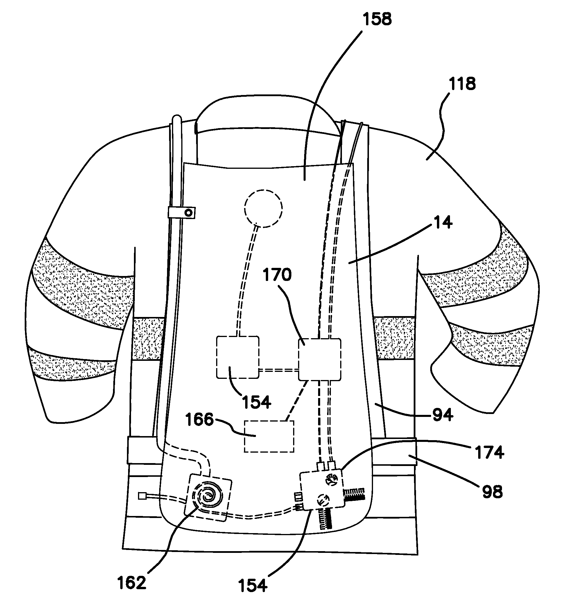
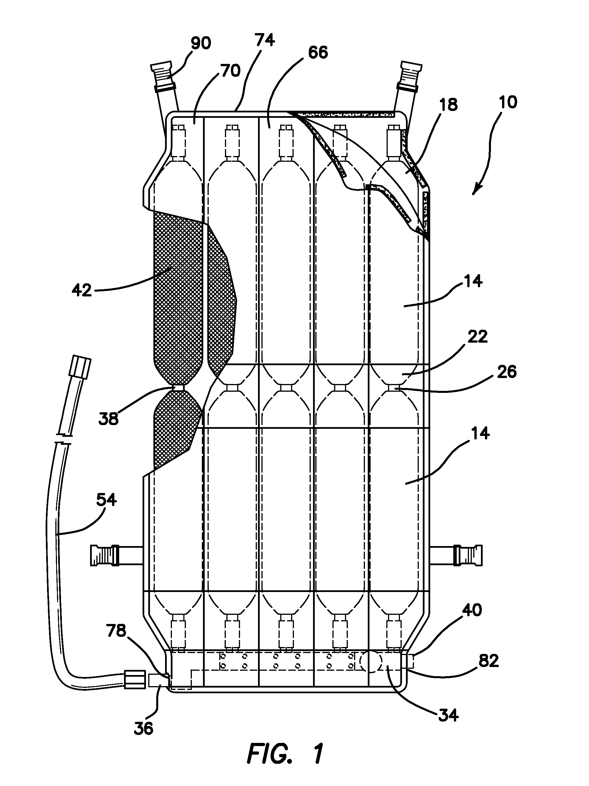
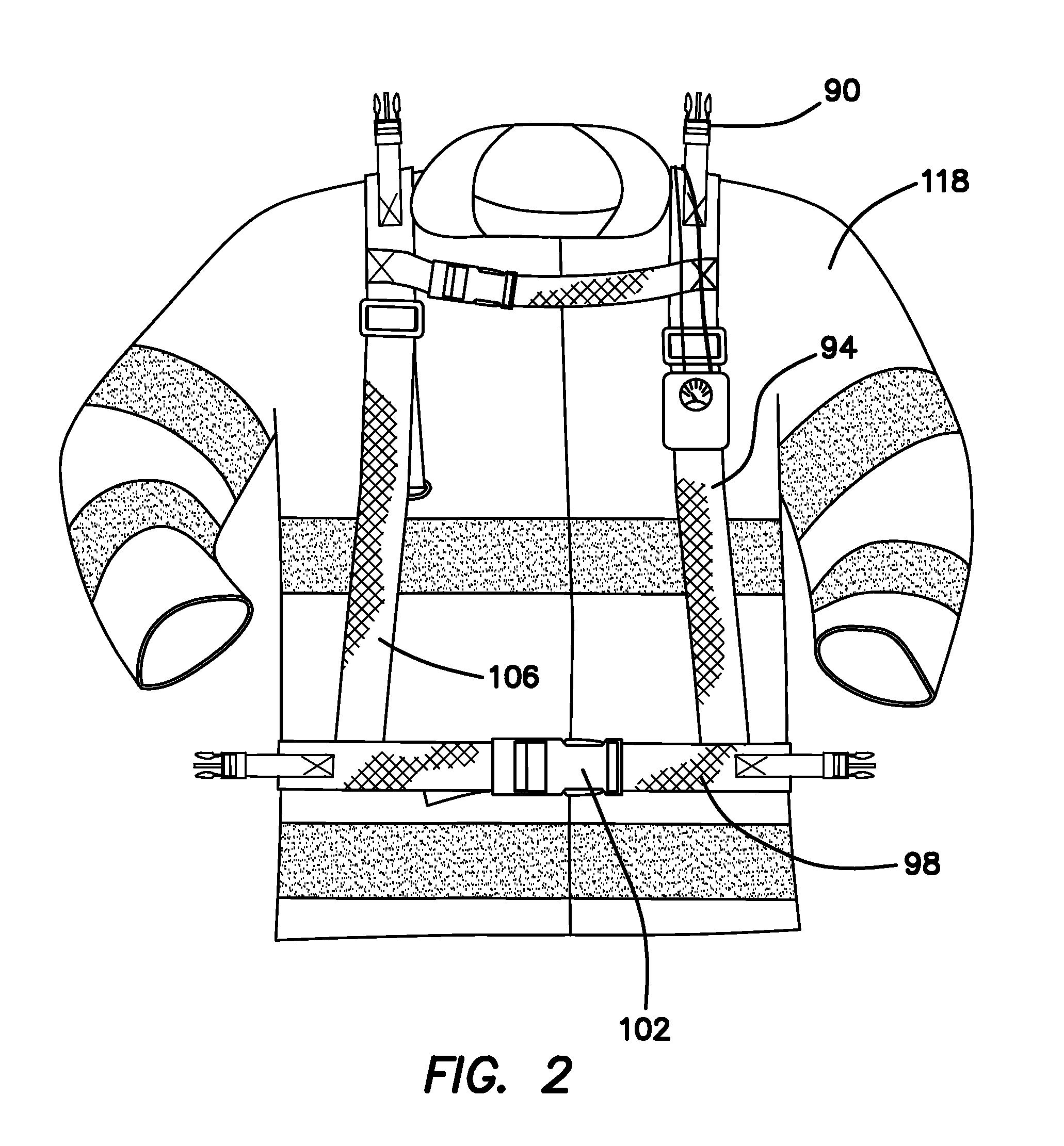
[0061](1) FIGS. 1-20 illustrate an articulated firefighter breathing pack 10 providing the desired features that may be constructed from the following components. As illustrated in FIG. 1, a plurality of polymeric pressure vessels 14 is provided. Each of the vessels 14 has an elongated cylindrical shape, a first end 18 and a second end 22. Each of the first 18 and second 22 ends has an attached section of flexible conduit 26. Each of the sections of flexible conduit 26 is attached to either a sealing fitting 30, another section of flexible conduit 26 attached to another vessel 14 or a manifold 34. Each of the pressure vessels 14 is attached to at least one other pressure vessel 14 with one of the sections of flexible conduit 26. The pressure vessels 14 and the sections of flexible conduit 26 are encased in high strength fiber material 38. The pressure vessels 14 are wrapped with a high strength ballistic ribbon material 42. A manifold 34 is provided. The manifold 34 is connected to ...


PUM

PropertyMeasurementUnit
Fractionaaaaaaaaaa
Pressureaaaaaaaaaa
Flexibilityaaaaaaaaaa

Abstract

An articulated firefighter breathing pack includes multiple polymeric pressure vessels connected together and to a flexible manifold with sections of flexible conduit. The pressure vessels and sections of flexible conduit are encased in high strength fiber material. The pressure vessels are wrapped in high strength ballistic ribbon material. The manifold provides connections for a high pressure regulator and an air fill source. A low pressure hose is connected to the high pressure regulator, a low pressure regulator is connected to the low pressure hose and a mouthpiece connected to the low pressure regulator. A pressure vessel container attaches the pressure vessels, the flexible conduit and the manifold to a harness having a waist portion and two vertical straps extending upwardly over the shoulders and back down to the waist portion. A utility belt provides mounting for equipment for the breathing pack including hoses, a power supply, electronic sensors and controls.

Description

FIELD OF INVENTION [0001]This invention relates to the field of portable breathing systems, and more specifically to breathing apparatus designed for use by firefighters.BACKGROUND OF THE INVENTION[0002]Firefighters regularly enter burning buildings to rescue persons and to protect property. These buildings usually contain large quantities of smoke and / or other gaseous toxic substances. In order to protect the firefighters from such harmful substances, portable breathing devices have been developed. Typically, these breathing devices comprise a high pressure metallic cylinder, a backpack for mounting the cylinder, a first stage regulator attached to the cylinder, a low pressure hose and a second stage regulator attached to a mouth piece. Devices such as this are relatively heavy and bulky. Such systems are potentially dangerous for the firefighter as they can easily snag on building features found in burning and collapsing structures. Further, because of the use of traditional metal...

Claims


Application Information

Patent Timeline
IPC IPC(8): A45F3/14A62B9/04A41D13/005
CPCA62B9/04A62B25/00A62B18/02A62B7/02
Inventor SANDERS, STAN A.
Owner SANDERS STAN A
Learn More