
Image forming apparatus

Inactive Publication Date: 2011-08-18
CANON KK
View PDF3 Cites 16 Cited by
  • Summary
  • Abstract
  • Description
  • Claims
  • Application Information

AI Technical Summary

Benefits of technology

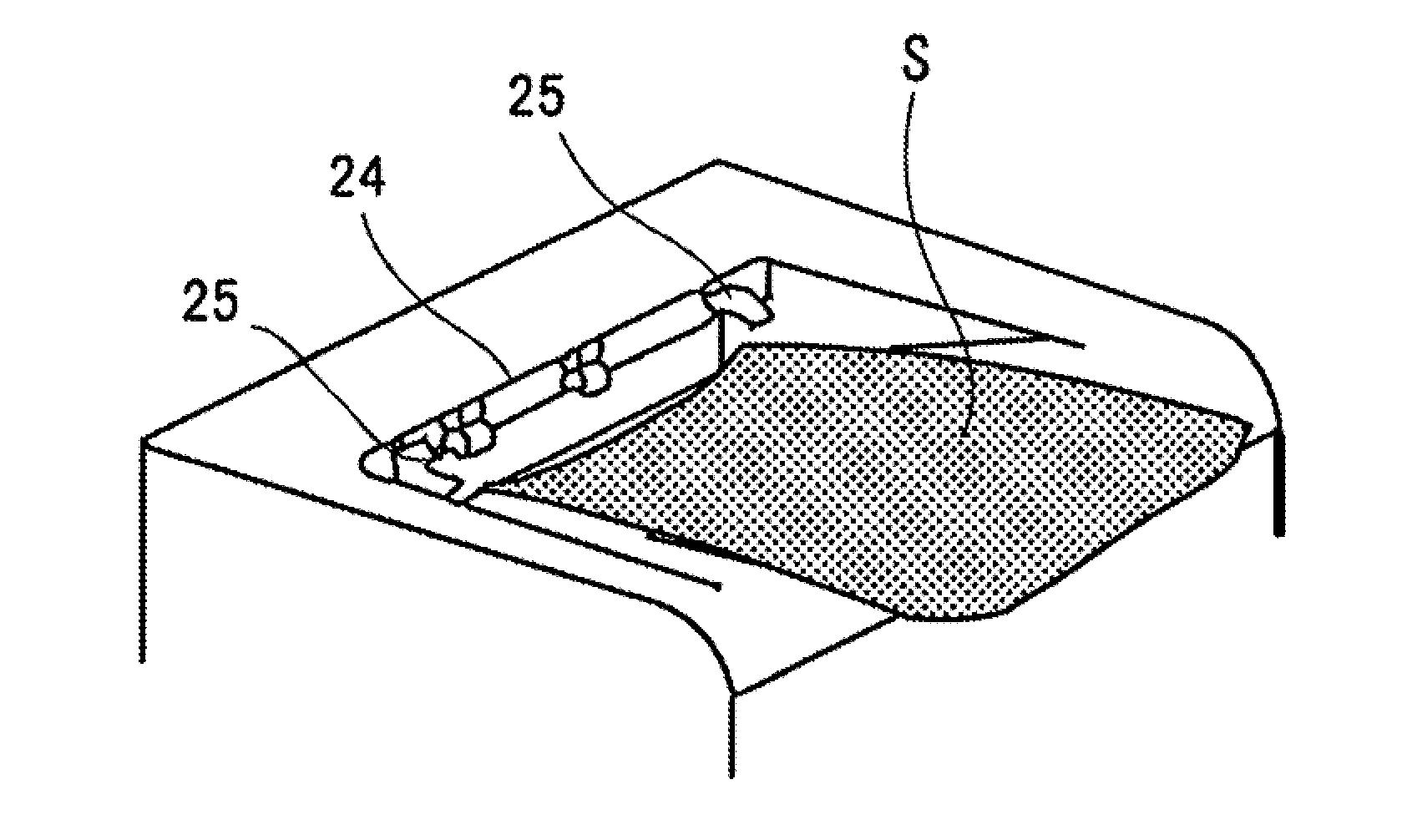
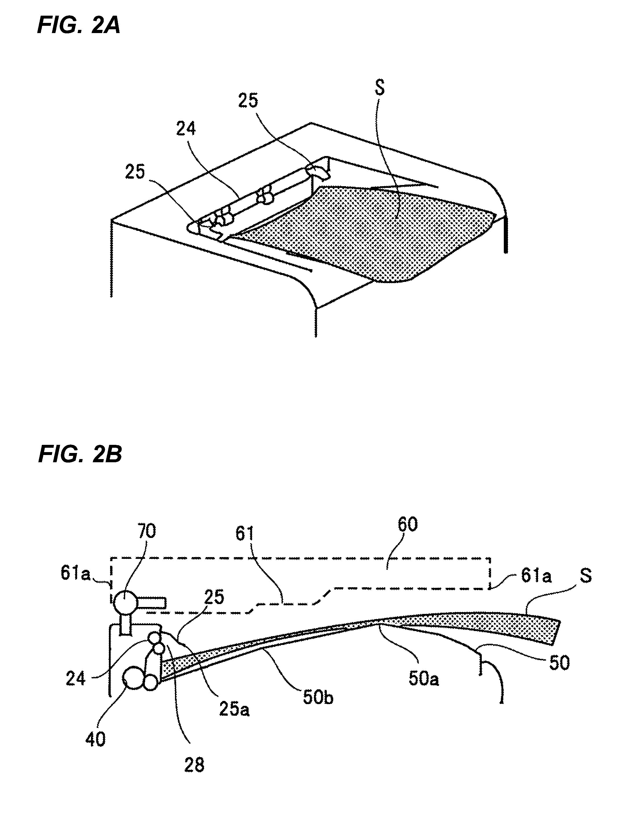
[0013]According to the present invention, a sheet is bent to reduce its curl by an image reading device and a sheet pressing member with an apex portion of the discharge tray being utilized as a fulcrum, so that even with a curled sheet, a stacking ability can be secured while effectively utilizing a discharge space.

Problems solved by technology

If the sheet in such a curled condition is stacked on the sheet discharge tray, the sheet may clog a discharge outlet and in this case, the stacked sheet is pushed out by the next discharged sheet, thereby causing damage to alignment or dropping the sheet from the discharge tray.
As described above, in a case of a curled sheet, the conventional image forming apparatus has an issue that a sheet stacking ability decreases and that the discharge space cannot be effectively utilized.

Method used


Image

  • Image forming apparatus
  • Image forming apparatus
  • Image forming apparatus

Examples


first embodiment

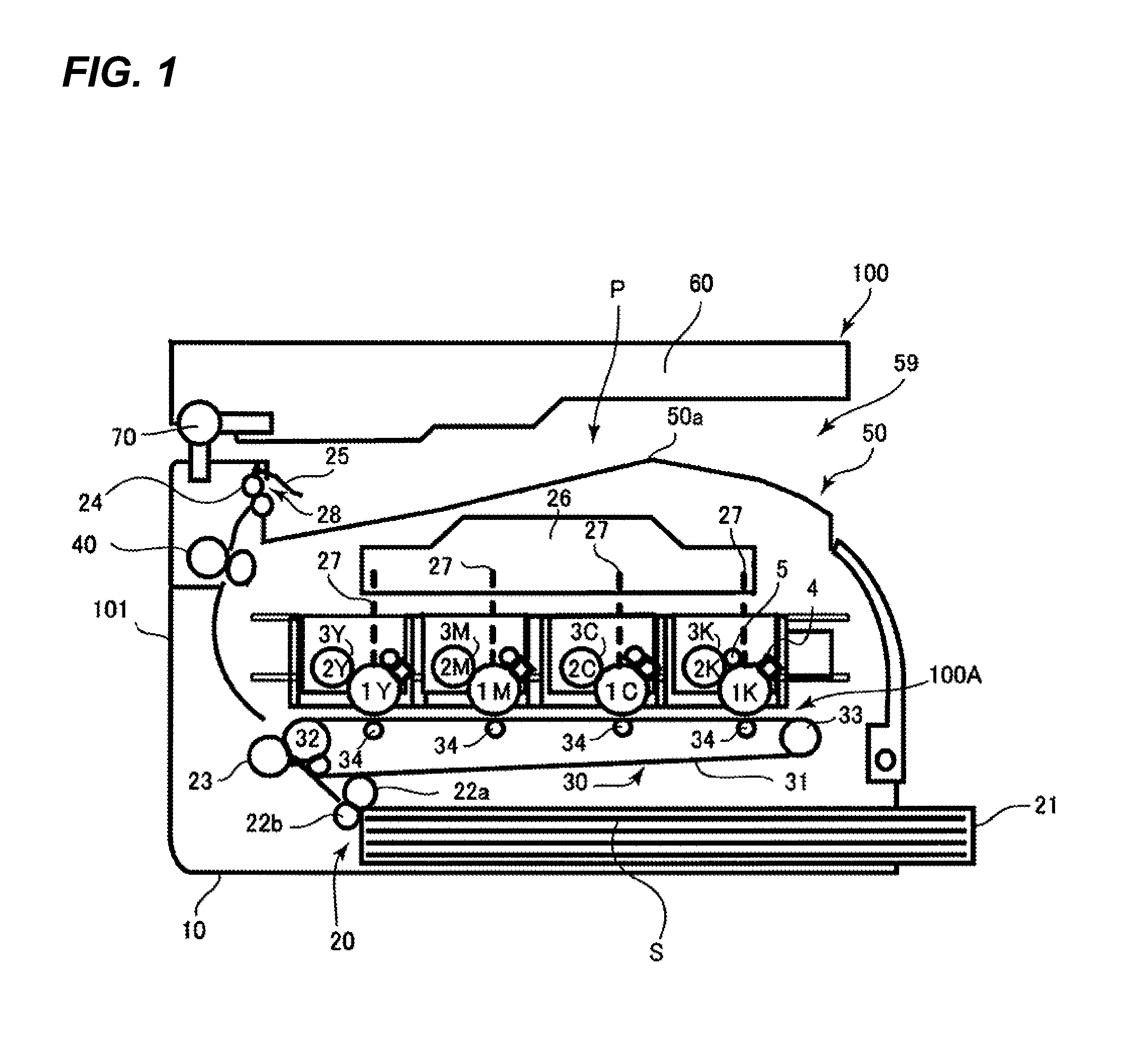
[0022]In the following, embodiments of the present invention will be described with reference to the drawings. FIG. 1 is a view illustrating an outline configuration of an image forming apparatus according to the present invention. FIG. 1 illustrates an image forming apparatus 100 and an image forming apparatus main body 101, in which an image reading device 60 configured to read an image on an original is disposed above the image forming apparatus main body (hereinafter referred to as a main body) 101. The image forming apparatus 100 is of an internally-sheet-discharging type that a sheet S on which an image is formed is discharged into a discharge space P formed in the main body 101.

[0023]A laser scanner 26 is disposed above the main body 101 and an image forming portion 100A is disposed below the laser scanner 26. The image forming portion 100A is configured to form an image under an electrophotographic system, in which four process cartridges 3 (3Y, 3M, 3C, 3K) for forming toner...

second embodiment

[0053]Next, the invention will be described. FIG. 5 is a view illustrating a configuration of a discharge space of an image forming apparatus according to this embodiment of the present invention. In FIG. 5, the same symbols as those in FIG. 3 represent the same or corresponding portions.

[0054]FIG. 5 illustrates an inclined surface 62 which is formed at the front end of the bottom surface 61 as the downstream end in the sheet discharge direction and is positioned closer to the image reading device than the second straight line 52. The inclined surface 62 making up a bottom surface inclined as described above is provided so that, when the sheet discharged on to the discharge space P is not curled, the sheet is discharged and stacked on the discharge tray without abutting the bottom surface 61.

[0055]Further, a turning member 63 as a projecting member is attached to the inclined surface 62 in a pivotally movable manner, and has a width enough to press the entire width of the sheet or t...


PUM

PropertyMeasurementUnit
Lengthaaaaaaaaaa
Sizeaaaaaaaaaa

Abstract

The present invention provides an image forming apparatus which can secure a stacking ability even when a paper is curled.An apex portion is provided downstream in the sheet discharge direction with respect to a center of gravity of the sheets discharged on the discharge tray, and an upstream portion in the sheet discharge direction of the sheet is pushed downward by the image reading apparatus, with respect to a downstream end in the sheet discharge direction of the sheet stacked on the discharge tray, at the downstream portion in the sheet discharge direction with respect to the apex portion of the discharge tray, and the upstream portion of the sheet is pressed by a flag while the downstream portion in the sheet discharge direction of the sheet is bent with the apex portion of the discharge tray.

Description

BACKGROUND OF THE INVENTION[0001]1. Field of the Invention[0002]The present invention relates to an image forming apparatus configured to discharge a sheet on which an image is formed to a space between a main body of the image forming apparatus and an image reading device and, in particular, to a structure to prevent a disorder in a stack of discharged sheets.[0003]2. Description of the Related Art[0004]Conventionally, as an exemplary image forming apparatus, other than facsimile machines or printers, there exists an image forming apparatus in which an image reading device is additionally arranged on a main body of the image forming apparatus in order to add another function such as a copying function. In a case of such an image reading device, since the apparatus grows in size, a space is provided between the image reading device and the main body of the image forming apparatus to discharge sheets thereinto, thereby achieving space saving.[0005]Herein, the image forming apparatus ...

Claims


Application Information

Patent Timeline
IPC IPC(8): B65H31/00
CPCB65H31/02B65H31/26B65H2801/06B65H2405/1113B65H2405/11151B65H2301/51214B65H2405/115
Inventor YAMAGUCHI, NORITOMO
Owner CANON KK
Learn More