Magnetic yoke, micromechanical component, and method for the manufacture thereof

a micromechanical and magnetic yoke technology, applied in the field of magnetic yoke, can solve the problems of requiring considerable effort, requiring relatively expensive assembly and joining techniques, and being relatively expensive to realize such voltages

Inactive Publication Date: 2011-08-18
ROBERT BOSCH GMBH
View PDF23 Cites 36 Cited by
  • Summary
  • Abstract
  • Description
  • Claims
  • Application Information

AI Technical Summary

Problems solved by technology

From a technical standpoint, it is relatively costly to realize such voltages, especially as there are risks of a sparkover or pull-in.
However, when working with a micromechanical component having a magnetic drive, the assembly and joining techniques are often relatively costly.
Therefore, considerable effort must be expended, in particular, to manu

Method used


Image

  • Magnetic yoke, micromechanical component, and method for the manufacture thereof
  • Magnetic yoke, micromechanical component, and method for the manufacture thereof
  • Magnetic yoke, micromechanical component, and method for the manufacture thereof

Examples


first specific embodiment

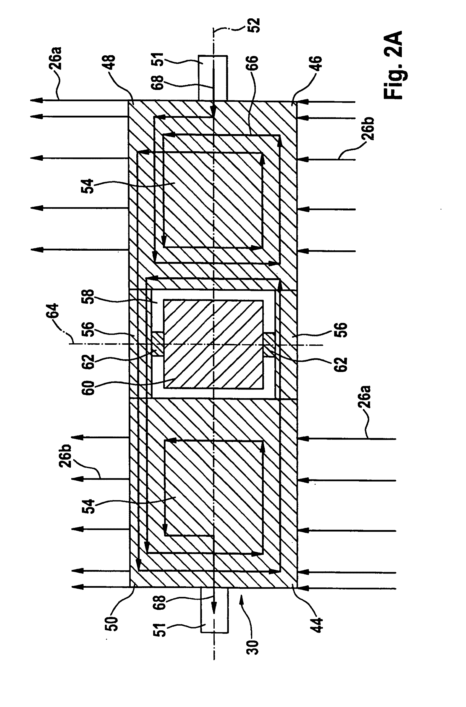
[0040]FIGS. 2A and 2B show a plan view and a lateral view of an intermediate frame for illustrating the micromechanical component.

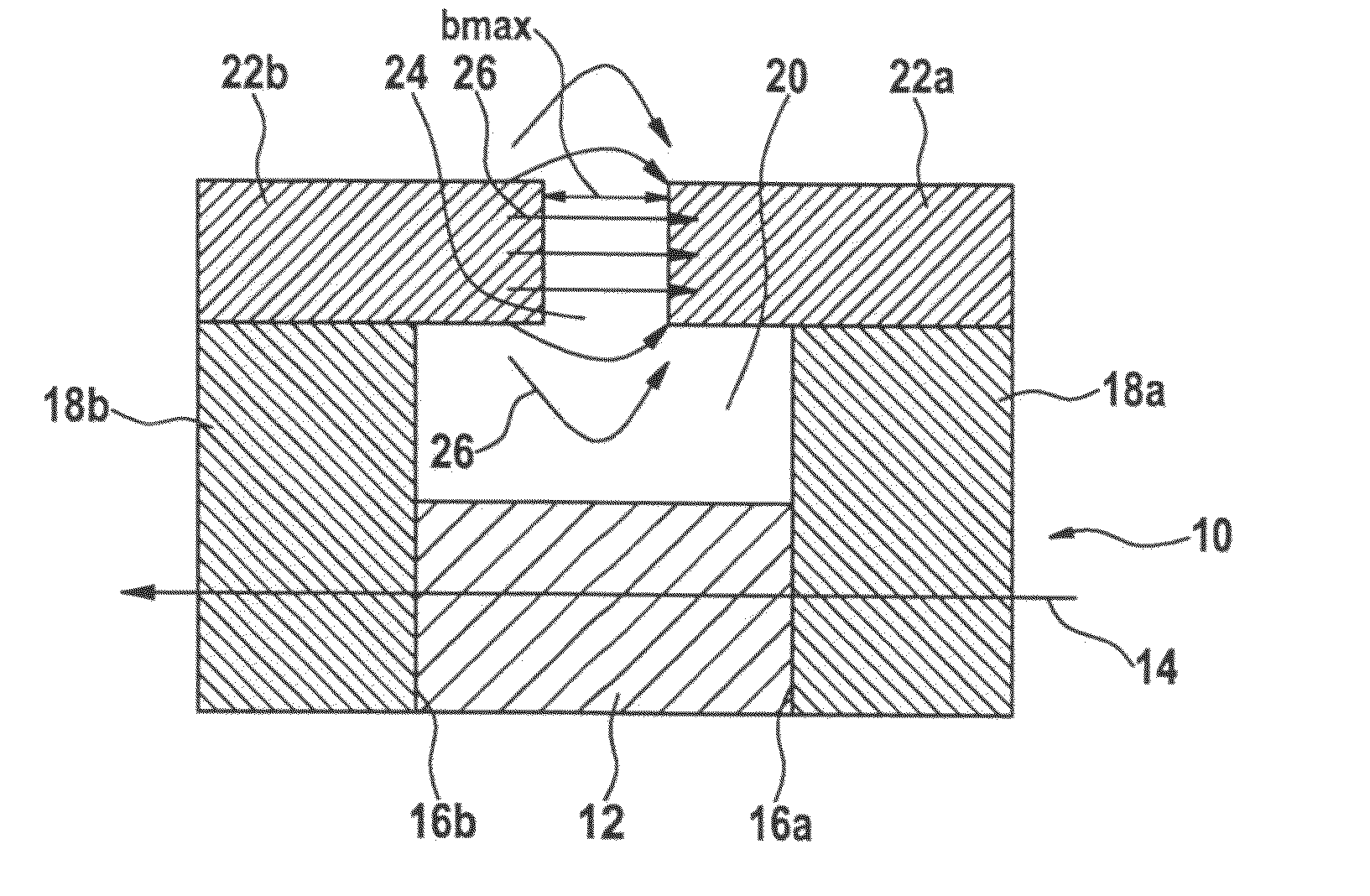
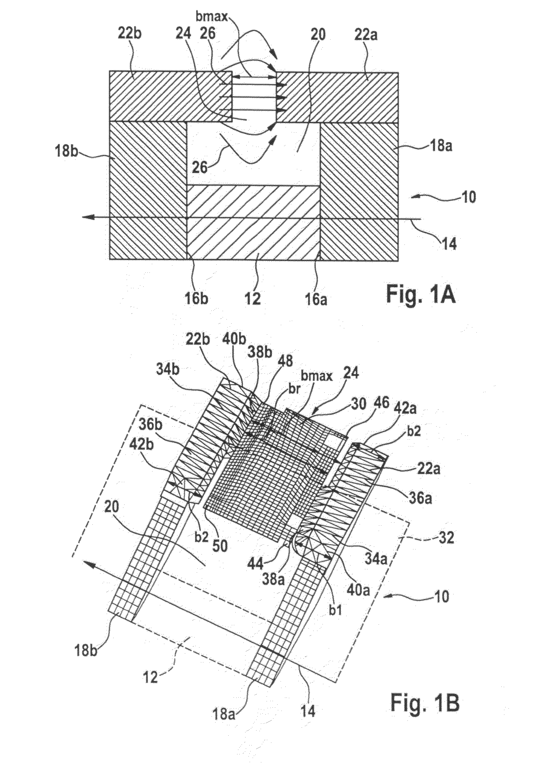
[0041]Intermediate frame 30 (inner plate) schematically reproduced in FIG. 2A is connected via two outer springs 51 to a holder (to an outer frame) (not shown). The holder encompasses a magnetic yoke (not shown) that is designed as an asymmetric magnetic yoke. Thus, intermediate frame 30 is fixed in the magnetic yoke. The magnetic yoke corresponds to the specific embodiment of FIGS. 1A and 1B, for example. Therefore, the design of the magnetic yoke is not discussed here in greater detail.

[0042]The two outer springs 51 extend along a first rotational axis 52, about which intermediate frame 30 is rotatable opposite the holder. The two outer springs 51 are designed as torsion springs, for example.

[0043]At one side adjacent to a first pole shoe of the magnetic yoke, intermediate frame 30 has corners 44 and 46 and, at one side adjacent to a second pole shoe of...


PUM

PropertyMeasurementUnit
Timeaaaaaaaaaa
Angleaaaaaaaaaa
Widthaaaaaaaaaa

Abstract

A magnetic yoke (10) having a magnet (12) having a magnetization direction (14) on which a first yoke arm (18a) and a second yoke arm (18b) are mounted in such a way that the magnet (12) and the two yoke arms (18a, 18b) define a yoke intermediate space (20) extending from a front side to a rear side of the magnetic yoke; and first pole shoe (22a) configured on the first yoke arm (18a) and a second pole shoe (22b) configured on the second yoke arm (18b), between which a yoke gap (24) is located; the first pole shoe (22a) having a first width (b1) at a first end (40a) on the front side of the magnetic yoke (10), in parallel to the magnetization direction (14) of the magnet (12), and having a second width (b2) unequal to the first width (b1) at a second end (42a) facing opposite the first end (40a) on the rear side of the magnetic yoke (10), in parallel to the magnetization direction (14) of the magnet (12).

Description

BACKGROUND OF THE INVENTION[0001]1. Field of the Invention[0002]The present invention relates to a magnetic yoke. The present invention also relates to a micromechanical component. Moreover, the present invention relates to a method for manufacturing a magnetic yoke and to a method for manufacturing a micromechanical component.[0003]2. Description of Related Art[0004]To permit adjustment of an adjustable control element relative to a fixedly mounted holder, a micromechanical component can have a magnetic drive, an electrostatic drive and / or a piezoelectric drive. The adjustable control element is a mirror plate, for example, which is adjustable by the drive about at least one rotational axis, preferably about two rotational axes.[0005]In comparison to a comparable component having an electrostatic drive, a micromechanical component having a magnetic drive has the advantage that comparatively high torques can be achieved at technically reasonable current intensities of less than 100 ...

Claims


Application Information

Patent Timeline
IPC IPC(8): H01F3/00H01F7/06B23P11/00
CPCG02B26/0841G02B26/0858H01F7/0231Y10T29/49826H01F7/066H02K33/18Y10T29/49071H01F7/0273
Inventor PIRK, TJALFPINTER, STEFANMUCHOW, JOERGFRITZ, JOACHIMFRIESE, CHRISTOPH
Owner ROBERT BOSCH GMBH
Why Eureka
Try Eureka