Unlock instant, AI-driven research and patent intelligence for your innovation.

Image capture apparatus and method

a technology of image acquisition and axes, applied in the field of image acquisition apparatus, can solve the problems of wasting time in realigning axes, vignetting or the like in the iris, user of the apparatus, etc., and achieve the effect of convenient use for the inspector

Active Publication Date: 2011-08-18
CANON KK
View PDF10 Cites 19 Cited by
  • Summary
  • Abstract
  • Description
  • Claims
  • Application Information

AI Technical Summary

Benefits of technology

The invention is an ophthalmic apparatus that can capture both a tomographic image and a fundus image of an eye. It uses two beams of light to achieve this. The apparatus also has a determination unit that can determine if the irradiation position of the first beam is within a range where the fundus image can be captured when the eye is irradiated with the second beam. This is done by using infrared light to pre-image the eye and gather information about the shift in the irradiation position. The apparatus is easy to use and can provide valuable information for diagnostic purposes.

Problems solved by technology

As a result of this, however, there is a problem in that when a fundus image is acquired in a state in which the optical axis of the illumination optical system is shifted away from the ocular axis after the tomographic image is acquired, the irradiation light toward the anterior ocular segment causes vignetting or the like in the iris of the anterior ocular segment.
Thus, the user of the apparatus (hereinafter, the inspector) may have wasted time in realigning the axes prior to beginning the fundus imaging.
On the other hand, it may be very cumbersome for the inspector to determine whether or not alignment is required before the fundus imaging after the tomographic imaging, causing a reduction in diagnostic efficiency.

Method used


Image

  • Image capture apparatus and method
  • Image capture apparatus and method
  • Image capture apparatus and method

Examples


first embodiment

[0019]The first embodiment focuses on a configuration example of a method of controlling an optical image acquisition apparatus to which the present invention is applied.

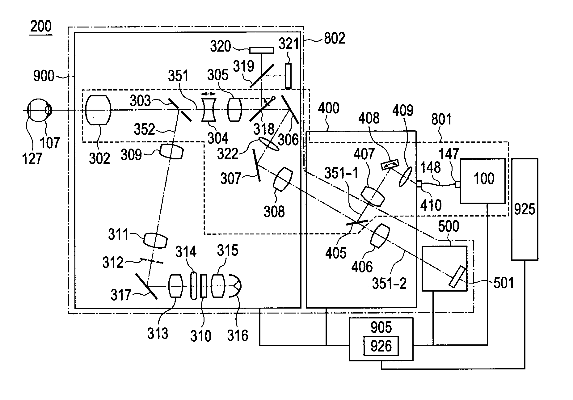
[0020]The optical image acquisition apparatus of the present embodiment includes a tomographic imaging portion which captures a 3D tomographic image of a fundus of an eye using information based on an optical interference. The optical image acquisition apparatus also includes a fundus imaging portion which images a 2D fundus image using an observation pupil diameter larger than that of the tomographic imaging portion.

[0021]An example of an ophthalmic apparatus is illustrated in FIGS. 4A and 4B.

[0022]FIG. 4A is a side view of the ophthalmic apparatus 200, an interferometer portion 100, a fundus camera main body portion 900, an adapter 400, and a camera portion 500. Here, the fundus camera main body portion 900, the adapter 400, and the camera portion 500 are optically connected to each other.

[0023]The adapter 400 is ...

second embodiment

[0144]As the second embodiment, an ophthalmic apparatus having a configuration different from that of the first embodiment will be described.

[0145]The ophthalmic apparatus according to the present embodiment is different in configuration of the ophthalmic apparatus from that of the first embodiment in that an alignment is made under control of an actuator such as a motor.

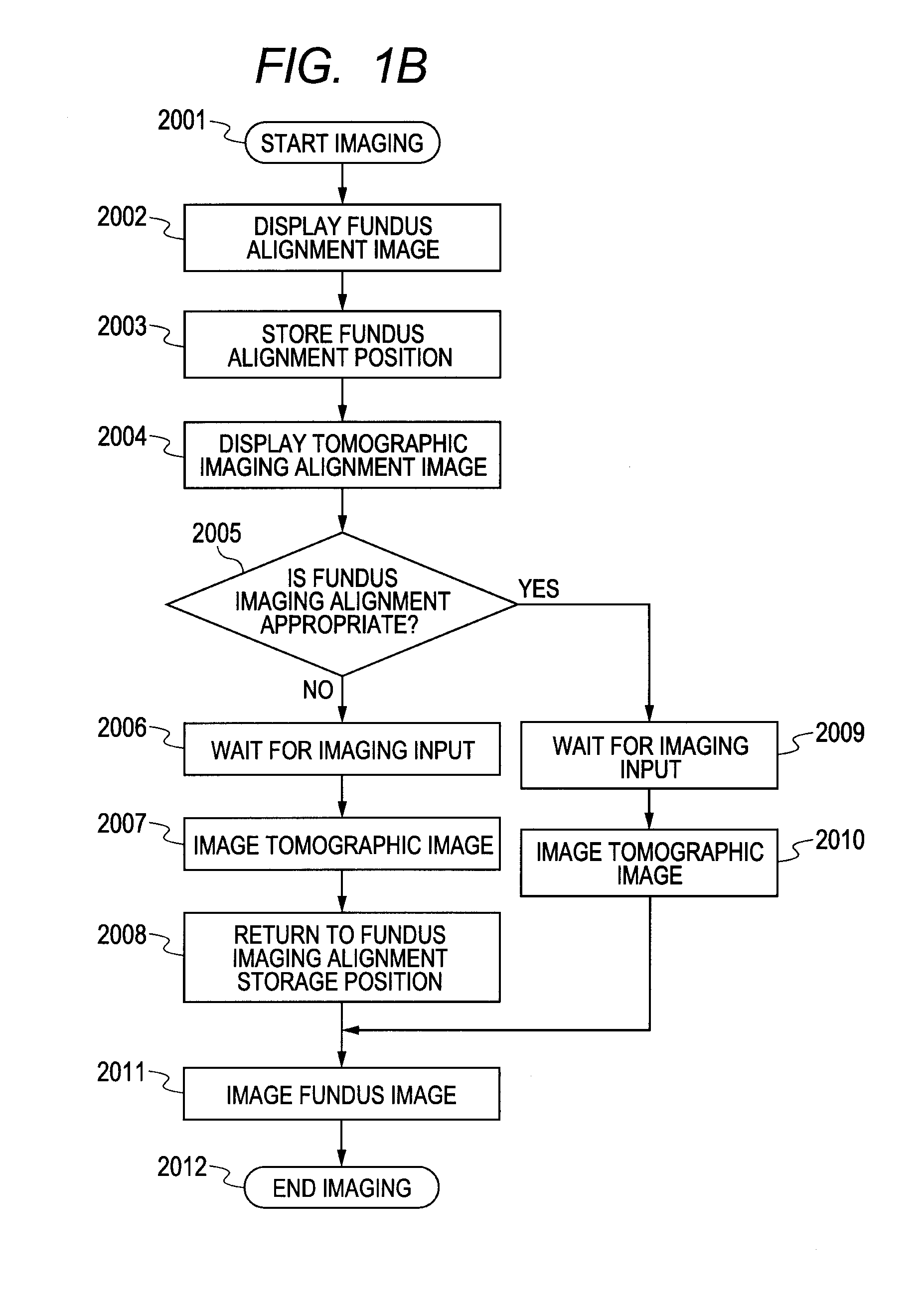
[0146]Further, the present embodiment is different in image acquisition method from the first embodiment in that fundus re-alignment is automated.

[0147]The ophthalmic apparatus according to the present embodiment is configured such that an unillustrated sensor in the ophthalmic apparatus of FIG. 4A reads the operation of the joystick 903.

[0148]Based on the amount of operation, the control circuit portion 905 and the personal computer 925 control the unillustrated actuator to move the optical head portion 953 for alignment operation. According to the present embodiment, an actuator is provided in each xyz direction i...


PUM


Abstract

It has been very cumbersome to determine whether or not alignment is required before the fundus image is acquired after the tomographic image is acquired, causing the reduction in diagnostic efficiency. An ophthalmic apparatus is provided to solve this problem, which comprises an irradiation unit that irradiates an eye to be inspected with a first beam for acquiring a tomographic image of the eye and a second beam for acquiring a fundus image of the eye, the second beam having a beam diameter larger than the beam diameter of the first beam; and a determination unit that, based on information indicating a shift amount between an irradiation position of the first beam in the eye and an ocular axis of the eye, determines whether or not the irradiation position of the second beam falls within a range in which the fundus image can be acquired.

Description

BACKGROUND OF THE INVENTION[0001]1. Field of the Invention[0002]The present invention relates to an image acquisition apparatus which acquires a fundus image and a tomographic image of an eye to be inspected.[0003]2. Description of the Related Art[0004]Japanese Patent Application Laid-Open No. 2007-252693 discloses an apparatus which partially integrates an optical system of optical coherence tomography (OCT) for acquiring a tomographic image of an eye to be inspected with an optical system of a fundus camera (an apparatus for acquiring a two-dimensional (2D) image of a fundus by visible light). In particular, when an operation button of a joystick provided on the fundus camera is pressed, a plurality of 2D tomographic images (known as cross-sectional or B-scan images) is acquired and then a fundus image is acquired by visible light as illustrated in FIG. 6A and the like.[0005]In general, the observation pupil diameters (the diameter of a beam emitted on an anterior ocular segment o...

Claims


Application Information

Patent Timeline
Patent Type & Authority Applications(United States)
IPC IPC(8): A61B3/15
CPCA61B3/14A61B3/15A61B3/102A61B3/12A61B3/1225
Inventor MUTO, KENJI
Owner CANON KK